
What are Median Filters?
Recapping, filtering is a method used to reduce noise and unwanted signals. Effective filtering is about reducing as much of an unwanted signal, while leaving as much of a desired signal as possible. So, you must always use median filters with the utmost care and understanding their functions thoroughly. It’s advisable to review filtered and unfiltered data to make sure nothing is missing.
What to Filter?
As mentioned in Part 1, median filters are very effective means of filtering high-frequency noise such as electrical noise and spiking, and low-frequency noise or drift. High-pass median filters are best suited to filter out low-frequency noise. Low-frequency noise can be caused by probe liftoff variations inside the tube or over the test surface, changes of deposit conditions over the surfaces of the material or changes in material, composition, geometry or thickness.
Median Filters
For example, in Table 1, where there are 11 samples in the data set, the middle value is sample 6 and equals 20. Figure 1 shows a line graph of the data presented in Table 1.
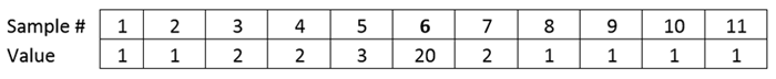
Table 1: Example data set with 11 data points

Figure 1: Line graph of the data presented in Table 1
High-Pass Median Filter
Definition: A high-pass median filter subtracts the median value of the sorted set of values, centered about the current data point, from the original set of values. The number of data points contained in that set is defined as the width of the filter.
Although trickier to explain, the concept is no more complicated than the low-pass filter discussed in Part 1. Indeed, one way to describe a high-pass filter is that it is the difference between unfiltered and filtered data using a wide, low-pass filter. The data in Table 2 will be used to illustrate how a high-pass median filter is created. Assume that the sharp peak, visible in Figure 2 at data point 19, is now the signal to be kept and the slow drift signal that goes from data points 1 to 33 is the noise to be filtered.

Table 2: High-pass median filter example data set with 33 data points

Figure 2: Line graph of the data presented in Table 2
-
Filter width – the median filter in this example uses 7 data points.
-
Centered about a current data point – using data point 1 to data point 7. Note that the center of this range of points is at data point 4.

-
Sorted values – take the 7 data points from data point 1 to data point 7 and sort them from smallest to largest. Note that the original data point numbers are no longer tracked.
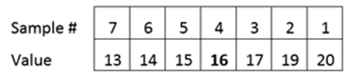
-
The median value of this set is the middle number in the row, which, in this case, is 16. Therefore the value of 16 becomes the low-pass median filtered value that will replace the original value at data point number 4.
-
This process is repeated for all of the data points, the results of which are shown in Table 3 and Figure 3. Note that the filtered data follows the drift signal in the original data fairly closely, but does not follow the abrupt deviation at data point 19. Also note that the filtered data is shorter by three data points at each end.
Table 3: 7 data point wide low-pass median filter of the data from Table 2

Figure 3: Line graph of the data presented in Table 3
The values in Table 3 are then subtracted from those in Table 2 and the result is shown in Table 4, below.
Table 4: Difference between the original data set in Table 2 and the low pass median filtered data set in Table 3

Figure 4: Line graph of the data from Table 2 with a 7-point high-pass median filter
An example of high-pass median filtered data appears in Figure 5 where the slow signal drift apparent in the upper C-scan is no longer present in the lower C-scan. High-pass median filters are used to correct coil-to-coil or scan-to-scan balancing issues and remove signal drift caused by liftoff, deposit variations, and material composition variations.

Figure 5: Magnifi® high-resolution C-scan of high-pass median filtered data
Similar to low-pass median filters, it is essential to choose an adequate filter width to ensure filtering doesn’t have unintended consequences. Unlike with a low-pass median filter, however, a high-pass median filter has fewer chances of attenuating defects when the filter is as wide as possible. In the example in Figure 5, the filter is 300 data points wide.
The chart appearing in Figure 6 illustrates the rapid attenuation of signal amplitude as the high-pass median filter becomes narrower.

Figure 6: Chart of signal attenuation with decreasing high-pass median filter width
Another undesirable result of the high-pass median filter is the possibility that it can distort the phase content. Therefore, it’s important to remember, particularly where phase analysis is used, to examine filtered and unfiltered data.
It’s also very important to note that high-pass filters will very effectively filter out many long and gradually occurring damage mechanisms such as long cracks, erosion, and wear. So, as a rule of thumb, a high-pass median filter’s width should always be at least three times the length of the longest possible defect to eliminate any possible detection loss.
The final consideration when using a high-pass median filter is more operational than analytical. High-pass median filters are very efficient at displaying data as properly balanced—as if all the channels or scans begin on the same baseline. Unfortunately, when using a high-pass median filter, an analyst cannot determine whether the probe is balanced when the data is collected. Data collected with an unbalanced or improperly balanced probe, can produce saturation, excessive noise, and signal distortion. Again, it’s always important to examine filtered and unfiltered data when using filters
The Takeaway
High-pass median filters are an effective means of mitigating long-duration noise events such as signal drift, imbalance, liftoff, material variations, and deposits. High-pass median filters should be as wide a filter as possible their degree of attenuation assessed on known defects before using them. As a rule, high-pass median filters should always be at least three times the longest possible defect and, as always, you should always examine filtered and unfiltered data, bearing in mind that high-pass median filters can distort phase.