
The Total Focusing Method (TFM) technique is getting more and more interest in the industry. Thanks to its high focusing capabilities, the technique leads to optimum spatial resolution and improved sensitivity for the detection of small indications. It has been recently included in standards, such as ASME V, and will continue to get more traction as developments continue.
Like many non-destructive testing (NDT) techniques, there are several requirements to follow in order to use it properly. One of them is Amplitude Fidelity.
Amplitude fidelity is a criterion that defines if the TFM image is properly discretized to preserve amplitude information, i.e. the pixels that compose the TFM image are small enough to properly measure the signal peak amplitude. If the TFM grid is too coarse an inspector could simply miss a small reflector, and if the operator uses amplitude-based techniques to size an indication, it may be underestimated.
The simple solution could be using a very fine TFM grid, but this would increase the computation time and seriously impact inspection productivity. With inspection speed being one of the challenges for TFM, particularly for units with a multiplexed architecture like 32x128 systems, it is important to find the right pixel size value and avoid oversampling the TFM image.
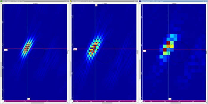
As an example, the following images are TFM reconstructions with pixel sizes of λ/20, λ/5 and λ/3, respectively. As the pixels get bigger, we can see that it is statistically possible to miss the maximum amplitude of the echo.
ASME V states that amplitude fidelity shall be preserved to 2dB or less, and that the process applied to check this fidelity be included in the qualified procedure. Other standards require 2dB if amplitude is used for sizing and 4dB if sizing does not rely on the absolute amplitude of the signal.
Some TFM systems tend to calculate a theoretical amplitude fidelity based on an amplitude error that depends mainly on the central frequency and bandwidth of the transducer. The theoretical amplitude fidelity doesn’t consider other parameters such as material properties (attenuation), wedge definition, position of the grid relative to them, sampling frequency of the FMC, range, etc. All these parameters have an impact on the shape of the ultrasonic beam. While the theoretical amplitude fidelity gives an approximate value for what the pixel size should be, standards clearly state that it must be experimentally measured on a test piece to be code compliant.
To simplify this task, Eddyfi Technologies has implemented an approach that follows the guidelines provided in standards for both the M2M Gekko® and Mantis™ portable flaw detectors. For a fixed position of the probe (no coupling issues), the system calculates TFM images incrementally moving them by a few steps. It extracts the maximum and minimum amplitude values and calculates the amplitude fidelity.
The process is as follows:
1. Capture™ software calculates several TFM images separated by 1/20th of a wavelength.
2. For each TFM, it records the maximum amplitude of each side-drilled hole.
3. It then calculates the amplitude fidelity for each side-drilled hole.
4. The procedure is successful if overall amplitude fidelity is maximum 2dB, or 4dB if sizing does not rely on the absolute amplitude of the signal.
5. Capture provides a table with the amplitude responses for all the holes and TFM positions as well as the increment amount used to calculate all the TFM.
The following video shows the amplitude fidelity process implemented in Capture. The configuration is:
- Gekko 64x128
- 64L5-G3 probe (pitch 0.6 mm) with SW55 wedge
- 64-element TFM using shear wave
- 35mm thick sample with three side-drilled holes
- The Auto button for TFM sets the pixel size to λ/5.
- For visibility purposes and to see the TFM move, we increased the increment amount to 0.1 millimeters. By default, it is set to λ/20.
You can see that the amplitude fidelity check passes for this particular case with speeds of over 100 mm/s. As the process is automated by the software, it is very fast and easy to use for any operator. The TFM proposed by Capture has all the tools to be code compliant: element check, wedge delay calibration, TFM calculation for all modes, amplitude fidelity, and TCG – all while maintaining the portable phased array ultrasonic testing (PAUT) with the fastest TFM on the market.
Stay Beyond Current and contact us to learn more about the Gekko and Mantis for fast, code compliant TFM inspections today.