What is a scan plan for weld inspection?
A scan plan is a documented set of inspection parameters and beam plots that define probe placement, probe motion, and the examined weld and HAZ volume for a given UT technique. It typically includes joint geometry, weld and HAZ boundaries, beam angles and paths, index offset or stand-off, and, for TOFD, probe center spacing (PCS) and intersection depth.
The goal is simple: prove in advance that the selected probes and settings insonify the required examination volume in a standardized and repeatable way.
What codes typically require in a scan plan (practical summary)
Most weld UT codes and standards expect scan plans because they document how coverage is achieved and how the procedure can be repeated consistently. A complete scan plan typically includes:
- Examination volume coverage for each technique (weld and HAZ)
- Cross-sectional joint geometry and thickness, including HAZ limits
- Search unit size, frequency, wedge, and configuration
- Beam plots for all angles used, including interaction with bevel faces
- Probe position and motion relative to the weld centerline (index offset, stand-off)
- For TOFD, probe center spacing (PCS), beam spread, and depth of intersection
Choosing the right scan plan: TOFD vs PAUT vs TFM (and why combining works)
Use the simplest technique that meets your coverage and sizing needs, then combine techniques when a single method leaves blind zones or sizing ambiguity.
| Inspection goal | Best first choice | Why | Common limitation |
|---|---|---|---|
| Through-wall sizing with strong crack detectability | TOFD + PAUT | Complementary detection and sizing strengths in one inspection | TOFD dead zones near lateral/backwall must be managed |
| General weld coverage with established acceptance rules | PAUT (sectorial) | Flexible angle set and bevel coverage | Amplitude-only evaluation requires incidence control (6° rule) |
| High-resolution imaging and repeatable characterization | TFM (often with PAUT context) | Defined imaging paths and controlled image grid | Must document ROI, paths, pixel size, amplitude fidelity validation |
| Thick sections (example 75–300 mm steel) | Multi-zone TOFD configurations | Zoning addresses intensity and coverage across thickness | More setups to qualify and execute |
Practical rule: validate coverage before scanning
Before production scanning, verify full weld and HAZ coverage on the required legs, identify dead zones, and confirm probe positions are physically achievable and repeatable with the intended scanner or manual setup.
Conventional UT
What to validate in a Conventional UT scan plan:
Confirm at least one probe angle examines the fusion faces at, or as near as possible to, normal incidence. Confirm element size and frequency support the required sound path without excessive beam spread that would limit small-flaw sizing.
Conventional UT is the main ultrasonic technique for the inspection of fusion-welded joints. It has been used for quite some time and International Standards such as ISO17640 or ASME V explain the requirements necessary to define the proper procedures for weld examinations such as personnel qualification, procedure demonstration/qualification, extent of volume to be scanned, and acceptance standards.
Two important parameters to choose are the angle of incidence and the element size when performing weld examination with UT. According to Standards, one of the probe angles used shall ensure that the weld fusion faces are examined at, or as near as possible to, normal incidence. The element size shall be chosen according to the ultrasonic path to be used and the frequency. The smaller the element, the shorter the near field limit, and the larger the beam spread in the far field meaning a lower capacity to size small indications. If small-flaw sizing is critical, document the expected focal spot size at the bevel and confirm it is compatible with your acceptance criteria.
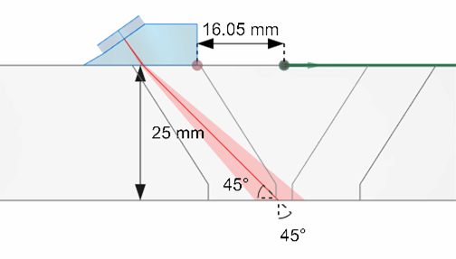
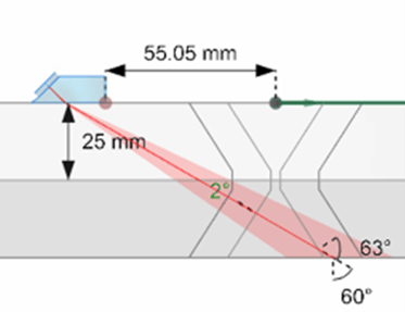
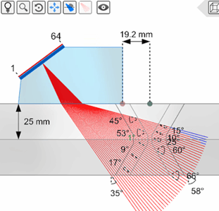
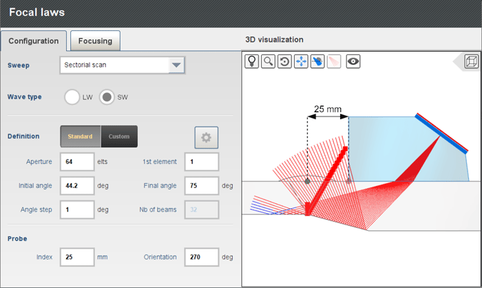
The following image shows a 9.5-millimeter (0.375-inch) 5-MHz conventional UT probe used to inspect a 25 millimeter (1 inch) 65° V-weld. We use two wedges: a shear 45° and a shear 60°. One can see several annotations in the 3D view: the component thickness, the index offset, the angle between the incident angle and the bevel (same side) on the second leg, the angle between the incident angle and the bevel (opposite side) on the second leg and the incident angle and the beam spread. The scan plan shows that it is barely possible to inspect the weld root using the wedge at 45°. The image on the right shows the scan plan for the SW60 wedge; we can see where the ultrasounds hit the bevel and have an idea of the focal spot size when they hit it. The angle with the bevel is 2°.
 |
 |
A Conventional UT scan plan is successful when it proves root and fusion-face coverage on the required legs and shows beam spread and focal spot size are compatible with the smallest indications you must detect and size.
TOFD
TOFD scan plan essentials
A TOFD scan plan should demonstrate adequate coverage by showing refracted angles, probe center spacing (PCS), beam spread, and depth of intersection. It should also identify expected dead zones near the lateral wave and backwall so they can be mitigated if they overlap the acceptance zone.
TOFD is described in ASME V and ISO 10863 as an ultrasonic image generating technique, which offers the capability of detection, location, and sizing. These standards provide tables with suggested frequency, beam angle, element size, and beam intersection based on the thickness of the component. In terms of scan plan, the probes shall be set up to ensure adequate coverage and optimum conditions for the initiation and detection of diffracted signals in the area of interest.
Cypher® provides the following information to allow operators to carefully choose and position their probes:
- refracted angle,
- probe center space (PCS),
- beam spread,
- depth of intersection.
Set PCS so the beam intersection covers the weld and HAZ through the required thickness, then confirm dead zones do not hide critical near-surface or near-backwall regions for your acceptance criteria.
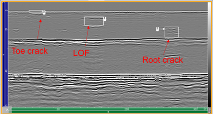
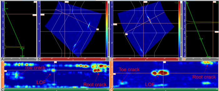
While TOFD has some “dead zones” due to the lateral and backwall echoes, a proper scan plan ensures maximum coverage and optimizes the chances of detecting defects close to those zones. In this example, both the toe crack and root crack are detected and sized properly.
 |
 |
For thickness ranges in steel 75 to 300 millimeters (3 to 12 inches), the beam divergence from a single element is not likely to provide sufficient intensity for good detection over the entire thickness. The examination piece shall be divided into multiple zones. The scan plan in Cypher PC allows the visualization of multiple TOFD configurations; up to eight pairs of TOFD are possible. Based on the acceptance criterion and/or the volume to be covered, offsets can also be applied.
For thick sections, zoning and multiple TOFD pairs are a scan plan decision, not an operator preference. The scan plan must explicitly show which zones are covered by which PCS and probe positions.
 |
 |
Phased Array
PAUT scan plan essentials
A PAUT scan plan should show weld and HAZ coverage, index offset or stand-off positions, the refracted angle set, near-field considerations, and beam incidence relative to bevel faces. This is critical when evaluation is amplitude-based.
Phased array scanning procedures for welds shall be established using scan plans that indicate the required stand-off positions for the probe to ensure volume coverage required and appropriate beam angles. The scan plan should show the beam coverage, the weld thickness, and the weld geometry. If the evaluation of the indications is based on amplitude only, the deviation from the normal to the weld shall not exceed 6°.
The scan plan in Cypher for PAUT provides the following information:
-
Weld and HAZ overlay
-
Index offset
-
Thickness
-
Refracted angles
-
Angle between refracted angles and bevels and if it exceeds 6° from normal
-
Near field
-
Positions of first and last elements
A proper PAUT scan plan should confirm:
- Full weld and HAZ coverage on the intended legs
- Beam incidence relative to bevel faces, including the 6° normal-incidence check when amplitude-only evaluation applies
- A sizing approach matched to flaw type (dB drop for bevel-aligned reflectors, tip diffraction when present)
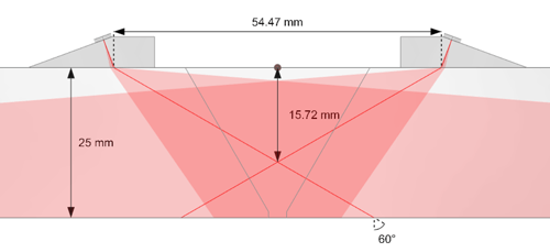
When weld geometry is not standard, importing the true profile into the scan plan reduces coverage uncertainty by letting you validate ray paths, skips, and bevel orthogonality against the real component shape before scanning. Operators can import dxf files that can then be extruded perpendicularly to the profile (planar extrusion) or revolve along the horizontal axis (revolution extrusion).
To prepare their scan plan, operators can then select any focal laws and see the corresponding ray tracing with reflections off any surfaces going full skip or up to 20 rebounds. This is a great visual aid to verify if the ultrasounds are perpendicular to a bevel for example, to select the proper angles to reach a particular location within a component, and to select the proper area for focalization. The following image shows the scan plan for a tapered weld using a projection focusing delay law. The focus points are aligned with the bevel same side as the probe. When using focusing, focal points are moving along the rays as well as allowing for inspections to position exactly the points of focus.
Taking into account the rebound off the taper when reconstructing the S-scan allows one to reposition correctly all the indications. This also helps greatly when it comes to sizing as echoes, especially tip diffraction, are repositioned at the right locations.
TFM
TFM scan plan essentials (what is different vs PAUT)
A TFM scan plan must define coverage and angles, but also imaging paths, ROI limits, and image grid density (pixel size), because these parameters directly affect detectability and sizing repeatability.
The past few years have seen more and more procedures using the TFM technique. Codes state that a scan plan with a standard and repeatable methodology for examination should be provided. The scan plan shall include a depiction of the required examination volume coverage, imaging paths, image grid density, weld joint geometry, number of examination scan lines, and search unit placement and movement with respect to the weld axis. TFM pixel size and processing must preserve amplitude fidelity. ASME V and ISO 23865 state that amplitude fidelity should be preserved within 2 dB, and the method used to verify fidelity must be included in the qualified procedure.
Document your pixel size, ROI, and validation method in the scan plan so results remain repeatable across operators and setups. If you reference a standard validation approach, link it in the body where operators will look for qualification evidence. (see Code Compliant Amplitude Fidelity for TFM).
The scan plan in Cypher for TFM provides the following information: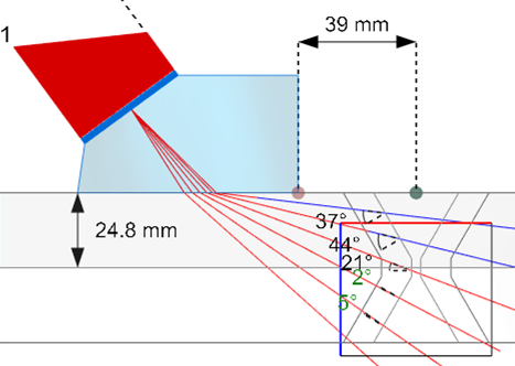
-
Weld and HAZ overlay
-
Index offset
-
Thickness
-
Refracted angles
-
Angle between refracted angles and bevels and if it exceeds 6° from normal
-
Near field
-
Positions of first and last elements
According to ASME, direct path alone shall not be considered adequate for full volume inspection. We have defined an ROI height that takes into account the first leg and second leg. The first leg is the T-T mode and the second leg is equivalent to the indirect mode TT-TT due to the symmetry with the backwall.
If direct path alone is not adequate for full volume inspection, the scan plan must explicitly define ROI height for first-leg and second-leg imaging paths, and it must state whether full coverage requires scanning from both sides using a multigroup configuration.
 For welded joints, the inspection needs to be carried out from both sides. We use two probes, one on each side of the weld, using a multigroup configuration.
Practical checklist: validate your weld scan plan before scanning
- Confirm weld geometry and HAZ boundaries match the job drawing and the actual cap profile.
- Confirm required examination volume coverage is explicitly shown for each technique (weld + HAZ).
- Verify probe frequency, wedge, and element size support the required sound path without near-field constraints that limit coverage or sizing.
- For PAUT, confirm beam incidence relative to bevel faces, including the 6° normal-incidence requirement when amplitude-only evaluation applies.
- For TOFD, confirm PCS and depth of intersection cover the acceptance zone and that dead zones are managed.
- For TFM, document imaging paths, ROI height (first leg and second leg if required), pixel size, and amplitude fidelity validation method.
- Confirm probe placement and motion are physically repeatable with the intended scanner or manual method.
- If full coverage requires both sides, document the multigroup configuration and probe positions on each side.
- Validate on a representative mockup before production scanning (detectability + sizing repeatability).
- Store the scan plan outputs (beam plots, offsets, PCS, ROI, paths) in the procedure package.
Cypher software releases have dramatically improved the possibilities to set scan plans for conventional UT, TOFD, PAUT and TFM. Operators can choose their probes, calculate their delay laws, and set their perfect standoff to ensure full coverage of their welds no matter what the UT technique is.
Stay ahead of the competition with our Beyond Current solutions, the Cypher and Panther for PWI/TFM inspections. Contact us for more information today.