NFT & NFA Comparison
NFT and NFA probes are only sensitive to internal defects. Their conventional channel(s) are generated from the coils that are wound around their circumference. These bobbin responses will yield a combined response for multiple circumferentially dispersed flaws. For this reason, multiple circumferentially dispersed flaws will yield a single indication on these channels. Of course, this is only true if the flaws share the exact same position along the tube’s length. This can be misleading because, for instance, the signal of multiple shallow flaws can give a similar response to a single much deeper flaw. This is even more important when considering that only the signal’s amplitude variation is used for analysis.
This can be observed on Figure 1a: the round bottom holes (RBH) sharing a common axial position are detected as a single defect by the NFT bobbin signal. Note that this data was obtained using the calibration tube A as pictured in Figure 2.
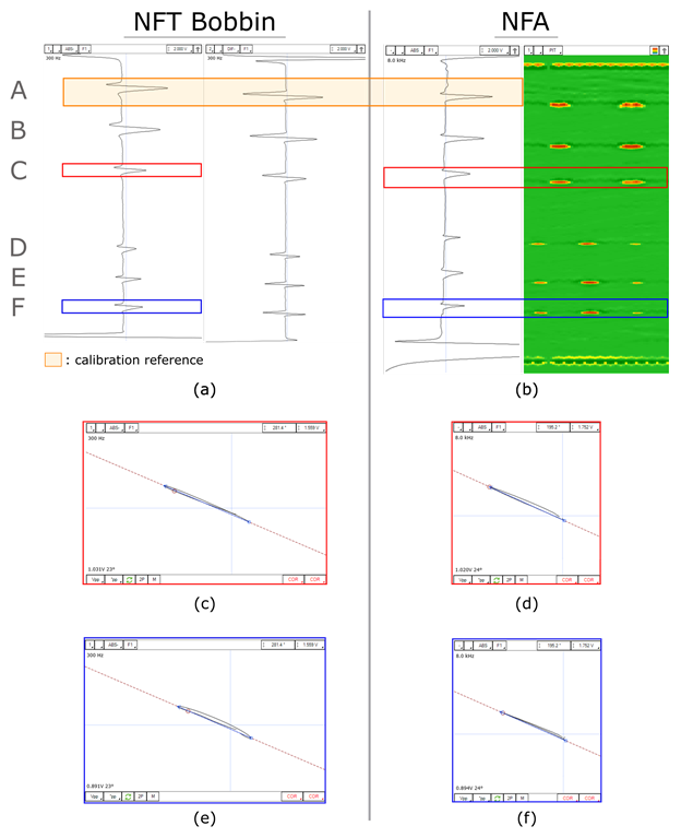 Figure 1. Data comparison of tube A for: (a) NFT Bobbin signal, (b) NFA signal responses, (c-d) NFT and NFA absolute channel readings of defects at location C and (e-f) of defects at location F. Note that both absolute channels were calibrated using the same reference.
On Figures 1c to 1f, we first notice that the amplitude readings are nearly identical for the NFT and NFA absolute channels when a common calibration reference is being used. With this in mind, we also note that the absolute channels (combined responses of all the defects present at a given location) yield a similar amplitude reading for positions C and F. However, as it is clearly depicted on the array part of the NFA signal, there are only two defects at C whereas there are three at location F. Albeit deeper and more critical, one could easily misinterpret the defects of location F as wider and shallower defects than they really are. This is where the NFA array information comes to light: its added mapping of the tube provides more information on the defect’s morphologies, and hence, a better assessment of the detected indications.
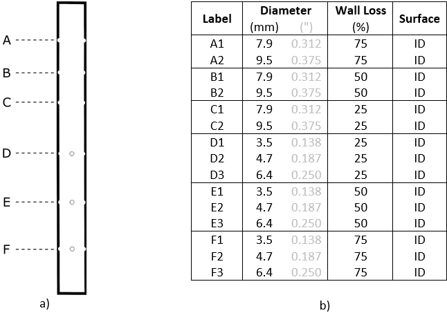 Figure 2. (a) Tube A representation and (b) its corresponding defects.
Cracks & Pitting Detection
Both NFT and IRIS techniques have their limitations when it comes to small internal pits or crack detection which can be overcome by using a NFA probe.
On the NFT side, these small indications are harder to detect due to their small volume loss. In turn, this means that the defect readings are harder to differentiate from the noise level which arises from the movement of the probe or from the irregular internal surface of the tube.
For IRIS, one common limitation is the impact of some defect profiles which do not allow the collection of the reflected ultrasonic wave pulse – it gets scattered due to geometry and does not return to the collecting transducer. Figure 3 shows an intuitive representation of this limitation: the RBHs appear as black spots meaning that no data was collected from these regions of the tube. Also, cracks cannot be detected using IRIS technique because their coverage is smaller than the focal spot of the focused ultrasonic wave packet. Simply put, the neighboring points of the crack (who are also within the focal spot) will reflect the UT wave as if no cracks were present. Hence, the measured inner diameter (ID) distance from the transducer will not be sensitive to the crack.
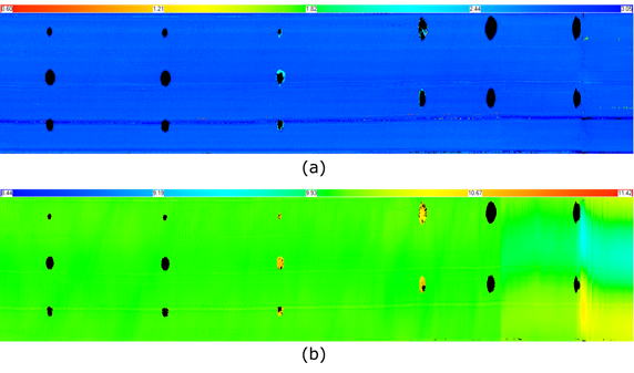 Figure 3. Tube A IRIS measurement results (a) wall thickness (WT), (b) front wall (FW). Limited echoes are collected for the RBHs.
To highlight the NFA crack detection advantage, a side-by-side comparison of the NFT, NFA and IRIS inspection results using a crack featuring tube is presented in Figure 4. As we can see on 4a and 4b, the bobbin readings (absolute channels) of both the NFT and NFA struggle to detect the ID cracks of the first portion of the tube. This is expected since the bobbins are sensitive over the whole probe circumference. Hence, these small cracks have a minimal impact when compared to the rest of the flawless surface of the tube. However, the NFA array coils pick up on the ID cracks. In fact, NFA is the only probe to detect the cracks because, as expected, we cannot clearly identify these with IRIS inspection technique (see Figure 4c).
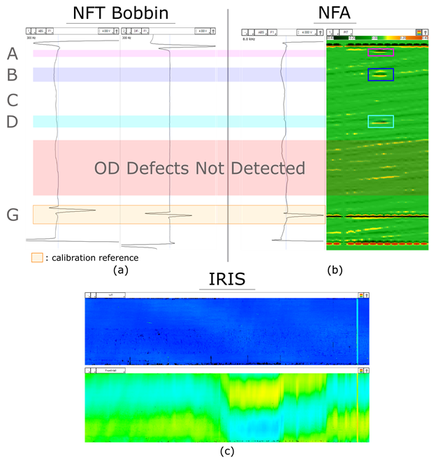 Figure 4. Signal response comparison of tube B for: (a) NFT bobbin probe, (b) NFA probe, and (c) IRIS WT and FW inspection results. Note that both NFT and NFA absolute channels were calibrated using the same reference.
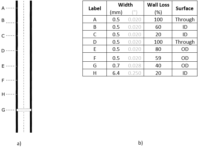 Figure 5. (a) Tube B representation and (b) corresponding circumferential notches and ID groove.
The Takeaway
To overcome the challenges of air cooler tubes inspection, the NFA solution combines portability, high scanning speed, and insights offered with C-scan imaging. This probe serves as an excellent ID detection tool capable of finding small indications and discriminating the circumferential extent of ID flaws. This last point provides valuable information regarding the relationship between the signal amplitude, the circumferential extent, and the flaw depth.
The NFA probe provides great information for overall assessment of asset integrity. This is especially true when combined with IRIS inspection since they complement each other well: IRIS yield WT measurements and NFA provides faster inspections with 100% tube coverage.
Eddyfi Technologies has gained the reputation as the industry leader for providing advanced non-destructive testing solutions to sectors who rely on the continued safe performance of their air conditioning systems as part of their everyday operations. Contact our experts to discuss your specific inspection requirements for a Beyond Current solution today.
Authors: Antoine Grégoire and David Aubé.