Specimen Menu
The Specimen menu alone allows great flexibility in setup and modification of the specimen. The ability to choose the geometry of the component from plate, pipe, fillet, nozzle, or import a 2D CAD file also helps save time in the setup. The ability to choose and modify the weld profile is a great advantage in that it allows the technician to optimize the setup for best results. Included in Capture software is the ability to include and modify the Heat Affected Zone (HAZ) as many codes require scan plans to include this to meet code requirements.
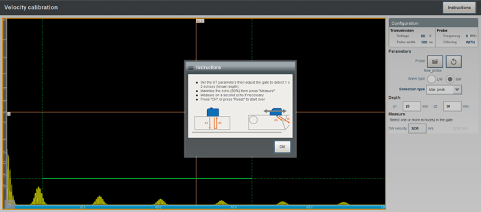
The ability to choose a between different types of material saves time in not having to look for a specific velocity and manually enter it in. If the material is an alloy and is not in the database, then a velocity calibration can be performed. There’s also the ability to select an Instructions button that allows the technician to follow instructions if the technician needs assistance in how to perform the calibration.
Probe Menu
The Probe menu allows the technician setting up the equipment to save time and data file size in that Capture version 3.3 allows the ability to choose the probe and wedge through a long list that has already been entered from different manufacturers. This allows the technician to not need to locate the probe parameters and manually enter them into the software while in the field. The filtering can also be adjusted through various parameters independently instead of choosing a bandpass filter which allows for better Signal-to-Noise-Ratio (SNR) based on the material being inspected. The sampling frequency can also be adjusted which allows for smaller data file size. Pulser adjustments can be made in down to a 24V level which is great for low thickness values and 1V increments.
Capture 3.3 allows the technician to calibrate the wedge velocity if the wedge velocity is not known. The angle height calibration for the wedge takes just a few steps and eliminates the need for a calibration block with reflectors. This makes the depth reading more precise since the wedge will start to wear after use and a new angle will be created from it. If the height calibration is not performed it will affect the depth values of reflectors in the material.
Scanner Menu
The Scanner menu allows one to choose between time-based scanning or encoded scans. The software has a long list of different scanners and encoders that can be used for inspection as well as the ability to manually enter in a custom encoder as well as a picture as a visual reference. Another benefit is the ability to calibrate the encoder/scanner in the same menu with the advantage of having instructions on how to perform the calibration.
Focal Law Menu
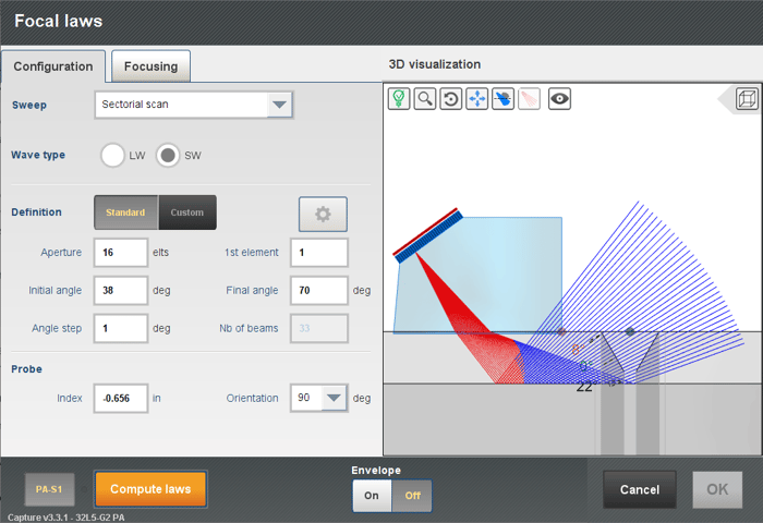
Capture 3.3 can perform sectorial, linear, and compound scans as well as import CIVA laws into the software. The software has great potential in that it allows the technician to choose between three different types of focusing: true depth, sound path, and projection. All these options give the technician the ability to optimize the focusing based on the desired reflectors or area of the component to be inspected. Under true depth focusing, the ability to adjust the initial and final depth independently allows the technician to optimize the scan plan to a desired bevel or area. The ability to adjust the sound path also and visually see where the region of focusing is also a great advantage. The onboard projection focus allows technicians to focus on a vertical plane which is beneficial for vertical bevels or vertical reflectors such as cracks.
One of the benefits that Capture 3.3 provides is the ability to view the near field which will allow the technician to optimize the aperture based on the inspection and component thickness. Being able to see what the effects of too small or too large of an aperture affects the calibration reflector can mean the difference between accepting or rejecting an indication as seen below:
Another advantage of Capture 3.3 is that it allows the user to adjust the delay, range, and gain to optimize the setup before going into the inspection menu. This saves setup time with not having to adjust these values twice.
Being able to adjust the index offset and visually see the incident angle to be a weld bevel is another great advantage that no other onboard software can provide. Being able to compute the laws in the setup menu also allows decreasing time for the scan plan design as it allows the technician to go live, see the calibration reflectors, and adjust the aperture as required for optimized signal response.
The ability to verify the maximum scan speed in the Focal Law menu also allows the technician to optimize the angle and angle resolution to get a higher scan speed if needed, without having to go into multiple menus.
The ability to adjust the skips/rebound allows the technician to show the client where a reflector is in the component without having to explain too much as the reflectors show where they truly are in the component.
The ability to take a screenshot of the final scan plan is also a great benefit of this software in that most codes and clients will require this to accept inspection reports.
Amplitude Calibration
Capture 3.3 can perform a basic Time-Corrected Gain (TCG), advanced TCG, and a Distance Gain Size (DGS) calibration. The advantage of advanced TCG is that it allows the technician to calibrate TCG on multiple reflectors in one pass as opposed to having to calibrate one reflector at a time. This dramatically decreases the time required to perform the calibration and setup time. And as stated previously, an Instructions button is included in the menu to assist the technician in performing the calibration.
Motion Menu
The Motion menu has a great advantage in that if the setup is created for inspecting pipes, the circumferential distance is calculated and entered by Capture. All the technician has to do is enter in a larger value by 1 or 2 inches to have overlap to make sure an indication at the start of the scan is not missed. The step for the scan is already set at 0.039 inches (1 millimeter) which most codes require at a maximum based on the thickness so no small indications are missed. A rotation of the component can also be adjusted to view the component in a 3D format or 2D if desired. This gives the technician in better understanding of the setup.
Display Menu
The Display menu allows the technician to choose from various layouts and adjust the windowpanes to the desired view such as an A-Scan, C-Scan, S-Scan, Top View, Side View, Echo Dynamics, 3D (analysis only). Choose from viewing the data from the entire A-Scan or only the gated region. The technician or level III can save the layout and use it for another setup if desired as well as send the layout file to another technician to have uniformity across all technicians. This helps when there are multiple technicians onsite with reporting that will be submitted to a client. Up to four different layouts schemes can be chosen in the setup.
Recording Menu
The Recording menu allows the technician to choose a data filename and select the Auto-Numerical naming scheme if desired. Another advantage is that the technician can choose the destination folder where the data file will be saved. The technician can create a folder and save it into said folder. This saves time because many times technicians could be onsite for a 12-hour shift and many scans will be performed and locating the correct files can become cumbersome. Data compression can also be adjusted between optimized, high resolution, reduced file size, and manual options. When optimized is chosen the compression factor is automatically adjusted. When choosing high resolution, the compression factor decreases so more A-Scan samples are recorded. When different data compression selections are chosen, the software will show what the compression factor is, maximum A-Scan samples, sound path resolution, and estimated data file size.
The test report can also be saved automatically with customizable inspection report information. New fields can also be created if a procedure or client requires certain data in the report.
Conclusion
The benefits of Capture GO and Capture PC software by Eddyfi Technologies are vast. It makes technicians’ work easier and reduces the time in relearning software as well as reducing setup time between all different inspection preparations for an upcoming job. The seamless use of Capture from the Mantis™ and Gekko® portable phased array ultrasonic testing instruments are identical in that they use the same software. There is no need to show up onsite or in a hotel room late at night trying to learn how to use different equipment and software. It’s the easiest software that I’ve used thus far in my time doing phased array. Someone can easily learn to operate the equipment in a very short time.
I invite you to contact our team with any questions about getting the most out of your inspections with Eddyfi Technologies advanced solutions designed to always keep you Beyond Current