
Have you ever performed trials where your perfectly set up bridge probe (or so you thought) ended up being so insensitive that you had to start over? Of course, you have. In this first of two articles, I’ll attempt to illustrate why it can be difficult to hit the mark with bridge probes (also known as impedance probes).
Eddy current testing (ECT) is a technique using a wire coil to produce a magnetic field around itself. When the coil approaches a conductive material, currents opposed to those in the coil are induced in the material — eddy currents. A defect in the conductive material disturbs the path of eddy currents. This creates a local magnetic field that changes the balance of the system. The imbalance can be detected by measuring the changes in impedance in the coil. It’s the telltale sign of the presence of defects. But how is this impedance variation measured?
So, an ECT bridge probe uses the impedance variation in its single coil (absolute) or several coils (differential) as a measure of its sensitivity to defects. Since Vout = I × Z, what we’re really measuring is a variation in voltage amplitude ΔVout.
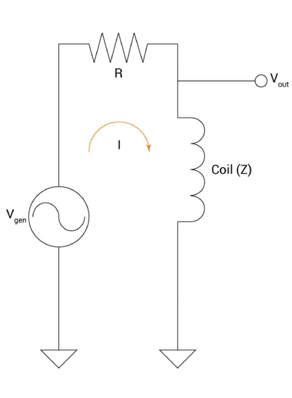
Basic Bridge Probe Circuit
Despite knowing all the working factors of the probe, it remains difficult to hit the spot where the output voltage variation relative to the probe’s coil frequency yields the best sensitivity to defects. In the context of ECT, the sensitivity of any impedance bridge probe is a function of ΔVout (mV) and the coil’s impedance (Z) and the bridge’s resistance (R), as illustrated by the following example:
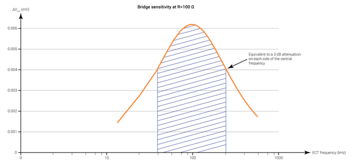
As you can see, the direct relation between these three elements yields a narrow, high-sensitivity bracket that’s easy to miss during setup, leading to a lot of trial-and-error. A coil frequency that’s too high or too low quickly has a major impact on the sensitivity of the probe.
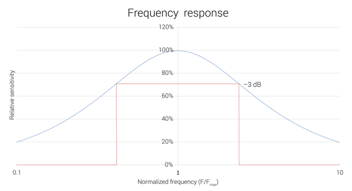
As a guideline, a 30% attenuation on both sides of the central frequency, equivalent to 3 dB, is acceptable. If we translate this into relative/normalized terms, sensitivity would be illustrated like this:
To circumvent this natural downside of absolute and differential bridge probes, the industry developed transmit-receive probes (also known as driver-pickup probes), which I delve into in part two of this series.
The Takeaway
To get the best results out of your bridge probe, it’s very important to understand that you must set it up in such a way as to get a coil impedance that is relatively close to the bridge’s resistance. Not to say that bridge probes don’t have advantages. They can, however, detect defects in all orientations (multidirectional probe). Transmit-receive probes can only detect defects in one direction — axial or transverse — depending on their configuration (unidirectional probe).
To further your reading, visit this page, where we present the various advantages and detection/sizing capabilities of the technology, and more. You can also visit our lines of surface and tubing probes to find the one that suits your individual inspection need.