
In my previous article, I discussed the frequency range of a sensitive bridge probe (impedance probe). From a sensitivity standpoint, bridge probes have a relatively narrow frequency range. This has the effect of binding bridge probes to the applications they’re tuned for. In the field, however, users usually need more flexible probes. Transmit-Receive (T-R) probes are such an alternative. The coil configuration in transmit-receive probes (also known as driver-pickup probes and reflection probes) have a relatively better sensitivity to defects, up to a certain point.
Advantages of Transmit-Receive Probes
Physically, T-R probes have two coils. The first coil generates eddy currents in the part under test. The second senses the variations in eddy currents in the component under test. In theory, the transmitter and receiver coils can be optimized separately to maximize their intended purposes. For example, the transmitter coil may produce a strong, uniform field in the vicinity of the receiver coil. At the same time, the receiver coil can be small enough to be sensitive to very small defects.
Limitations of Transmit-Receive Probes
Furthermore, T-R probes have a theoretically infinite frequency response because, having two coils, the relative sensitivity does not vary according to the frequency like in bridge probes. The sensitivity response of transmit-receive probes is still restricted to some extent. Despite them, however, the relative sensitivity range of the probes is still better than that of bridge probes.
From a sensitivity standpoint, however, T-R probes are not always better than bridge probes. If it were the case, no one would ever use bridge probes. Transmit-receive probes have two major limitations when it comes to sensitivity:
Low frequency = Thermal drift
At low frequencies (better probe penetration), the transmitter coil has a low impedance that increases its current. This leads the transmitter coil to generate a lot of heat, which has negative effects on the quality of returned signals and the equipment itself.
High frequency = Resonance
At the high end of the frequency range, the transmitter coil’s inductance can resonate with the parasitical capacitance of:
- Coils
- Probe cable
- Test instrument
- This leads to over-amplified and distorted signals.
The following graphs illustrate these limitations. As you can see from the current curve of a transmitter coil in a transmit-receive probe, the current is very high at low frequencies. This may result in overheating and thermal drift. In this example, the minimum frequency of the T-R probe is set to 100 kHz to avoid this.
Similarly, a T-R probe’s cable and coil impedance has an incidence. Set the frequency too high and the coils resonate with the cable. The peak in the following graph corresponds to the resonance frequency where the eddy current signal signature cannot be used. Here, to avoid resonance, the maximum frequency of the transmit-receive probe is set to about 500 kHz for a 20 m cable.
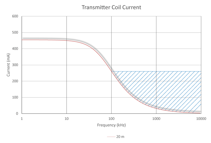
As you can see, under most normal conditions, transmit-receive probes may have a wider range of relative sensitivity to defects (100–500 kHz for the 20 m cable probe above). This may make them better than bridge probes in many applications where better flexibility is an asset.
However, this is only one aspect — relative sensitivity — to be considered when deciding what type of probe to use in an inspection project. Other considerations include the type of materials involved, the type of defects, the amount of liftoff, and many more, whether you are inspecting surfaces or tubes.
Visit our lines of surface and tubing probes to find the one that suits your individual inspection need.