When performing Phased Array Ultrasonic Testing (PAUT) or Total Focusing Method (TFM) inspections, a set of calibrations are required prior to examination. Operators need to check that all the elements of the array are working properly and compensate for lack of uniformity. A wedge delay calibration needs to be performed to ensure proper positioning of echoes. Finally, a Time Corrected Gain (TCG) is needed for calculation of the delay laws/TFM to ensure amplitude correction across all distances and beam angles. In this blog, we present the various tools offered with Capture™ software for easier calibration and more productive inspections.
Element uniformity
When performing an inspection, one must make sure that the results are not impaired by dead elements and/or loss of performance by some of the elements. To check the uniformity of the elements the probe is positioned on top of a block with clean and parallel surfaces, and a single pulser-receiver channel is selected to address each element. The following video shows the variation in sensitivity for a 64-element PAUT probe. One can see that there is no dead element and a maximum variation in sensitivity of about 3 dB. The number of inactive elements allowed is based on performance that needs to be achieved; no simple rule can be made.
Capture allows for a sensitivity compensation by applying a receiver gain to each element to provide an 80% response on all the elements. This gain is saved in a table that also allows activating/deactivating elements to see the influence of dead elements on the inspection performance.
Wedge delay calibration
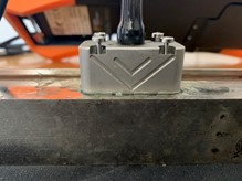
To calculate delay laws or TFM properly, the angle and height of the wedge need to be calibrated carefully. Improper measurements lead to wrong delay laws/TFM resulting in wrong angles and poor focusing.
Capture integrates a wedge delay calibration tool that automatically measures the angle and height of both flat (and AOD) and COD wedges. Operators just need to connect the probe to the wedge and the calibration tool detects the echoes off the wedge backwall fitting a line (for flat and AOD) or a curve (for COD) to extract the angle and height of the wedge. It also detects whether the first element is at the bottom or top of the wedge.
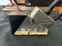
The following video shows the angle/height calibration for a SW55 wedge attached to the 64L5 probe used before. We tell the system that the first is at the top of the wedge even though it is at the bottom. We adjust the range and gain and position a gate to detect the backwall echo from the wedge. The system measures the wedge angle and height, which can be compared to the value previously entered. We can also see that the software automatically corrects the position of the first element.
Delay laws
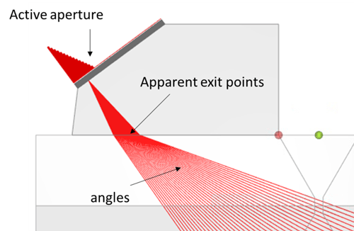
When a wedge is used to perform electronic and/or sectorial scanning, the sound path in the wedge material varies from one focal law to the next. The “apparent” exit point moves along the interface between the wedge and the sample, so a correction needs to be applied to compensate for this motion. The Capture delay law calculator takes the “apparent” exit point displacement into account to correctly position indications in the projection scan displays, i.e., the depth and angle within the test piece are correctly plotted. It is functional for all probes: linear, matrix, dual linear array (DLA) and dual matrix array (DMA), and for flat and curved components.
There are various delay laws available with Capture; learn more here.
Time Corrected Gain (TCG)
When doing PAUT, standards require that all individual beams used must be calibrated to provide distance measurement and amplitude correction over the sound path employed in the examination. While TFM doesn’t exactly create beams, each pixel is the result of a “delay law” applied to an array probe to focus the acoustic energy at that point. Amplitude calibration for TFM can thus be applied to have the same sensitivity for every pixel in the ROI.
In Capture, TCG is done using a calibration block with a series of identical side-drilled holes (SDH) or notches at different depths. The amplitude of each SDH is recorded for each angle for PAUT and pixel for TFM along a horizontal line, over the complete width, by moving the probe over the SDHs as shown in the following figure for TFM.
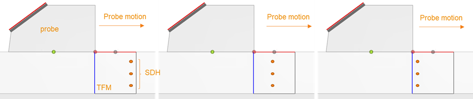
As the transducer moves, a persistence image is generated by retaining the maximum amplitude for each angle/pixel. A depth correction is then performed by determining the gain necessary to adjust the response of each SDH to the desired level, typically 80% screen height. The TCG process is summarized in the following videos.
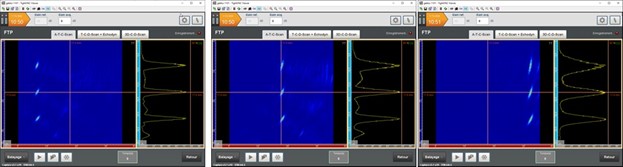
At the end of the TCG calibration, a distance measurement and amplitude correction are applied over the sound path employed (for PAUT) and vertical lines in the ROI (for TFM) in the examination. The following image shows TFM images of three SDH obtained for different mechanical positions. The echodynamic curves project the maxima of each row along the depth axis, allowing one to directly see the peak amplitude of the SDH. We can check that the amplitude of the three SDH is exactly the same (80%) for all positions.
Capture software for M2M portable PAUT and TFM instruments offers all the tools to perform calibrations according to standards. These tools have been optimized to offer ease of use and efficiency which equates to spending less time on calibration and more on inspection and analysis.
Contact our NDT experts to learn exactly how our industry leading software solution not only provides these efficient calibration wizards but also offers many other advantages to ensure maximum return on investment. Not ready to talk? No problem! Stay Beyond Current by checking out the top 7 questions you should ask when choosing your next phased array UT solution, and subscribe to our blog to have relevant NDT content delivered direct to your inbox.