Total Focusing Method (TFM) is an innovative ultrasonic technique that is revolutionizing the way we see defects. It was introduced to ASME code in 2019, and the ISO standard is entering the final stage before publication. Eddyfi Technologies has tremendously invested in improving the technique on its various systems among which its portable line: Mantis™ and Gekko®. Capture™ software version 3.2 brings even more features to TFM with improved productivity, multi-mode and multi-group capabilities making it the perfect toolbox for operators.
Eddyfi Technologies was the first NDT manufacturer to provide a portable Phased Array Ultrasonic Testing (PAUT) unit with TFM capabilities. Over the years, the technology has matured and gained interest from service companies and asset owners thanks to its improved sensitivity and focusing capabilities. Time Corrected Gain (TCG) has been implemented to ensure uniform amplitude with depth and position across TFM images. The experimental Amplitude Fidelity described in the ISO standard has been implemented to make sure that TFM images are properly discretized while avoiding oversampling them. With all the means in place, code compliant inspections have been made easy thanks to Capture.
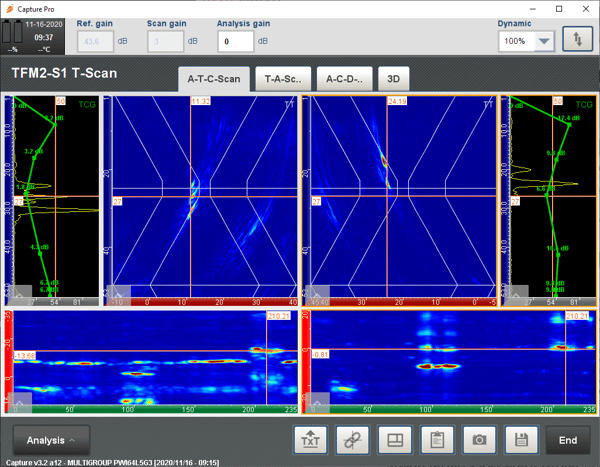
Standards require weld inspections be carried out from both sides of the weld. Capture 3.2 brings multi-mode and multi-group capabilities allowing inspectors to use several PAUT probes simultaneously on either side of the weld combining different TFM modes to look for defects. The following image shows examples of multi-group (top) and multi-mode (bottom) configurations for a 25-millimeter (1-inch) V-weld plate containing three defects: toe crack, lack of sidewall fusion, and root crack.

This feature makes sense if productivity is compatible with standard ultrasonic inspection methods such as conventional UT, Time-Of-Flight Diffraction (TOFD) or PAUT. TFM productivity in Capture has already been improved several times over the past few years by introducing techniques such as Plane Wave Imaging (PWI). However, as the number of groups/modes increase so does the need for productivity.
Capture 3.2 offers two more improvements for productivity. The first is the possibility to calculate the envelope of the TFM image. The envelope requires a reduced grid resolution to obtain the same amplitude fidelity using less pixels and thus improving productivity. The second one is an improvement in software/firmware architecture that allows a 60% scanning speed improvement for TFM images with less than 93 kpixels. While less pixels may suggest reduced image quality, Capture 3.2 introduces video smoothing combined with the envelope.
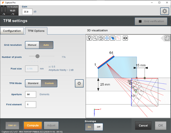
Scanning speed is one aspect of productivity but another is the time spent by an operator to prepare configurations and analyze the data. To help operators setup their TOFD, PAUT and TFM configuration, a scan plan tool has been implemented in Capture 3.2. The scan plan allows one to visualize the angle between the incident beam and the weld bevel and check if it is within six degrees, as requested per code; to display the near field zone and verify if it is possible to focus the energy; and display the beam spread for TOFD configuration to check the coverage of the TOFD inspection. This feature is available on all instruments: Mantis, Gekko and PC. The following image shows the scan plan proposed for a PWI/TFM inspection with the angles off the bevel (colors show if the angle is less than 6°), the near and far field information indicated by the red and blue colors, respectively, along the rays.

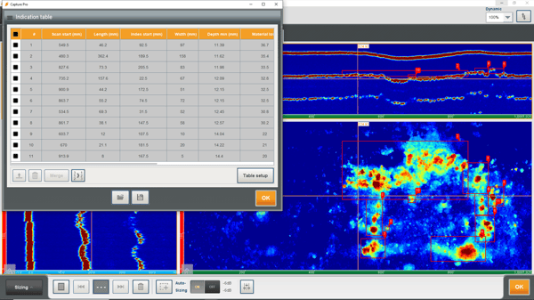
Data analysis is sometimes the bottleneck for making a decision related to the integrity of a component. Capture 3.1 offered a tool that allowed automatic sizing of the defect based on a decibel drop method. Capture 3.2 offers a similar tool for corrosion mapping inspection. An operator can define the thickness threshold for which indications should be detected and the thickness threshold until which they should be sized and Capture automatically detects all the indications within the area corresponding to this criteria and creates a table of indications. The table is fully customizable (length, width, remaining thickness, positions, etc.) and indications can be rearranged and merged. The following image shows an example of this feature on data acquired with the RMS PA scanner and Aqualock probe.

If you want to perform effective TFM inspections, look no further than Capture software to provide the precise, repeatable, and actionable data needed for efficient asset integrity management. Contact our friendly and knowledgeable experts to learn more today.


