
Chloride stress corrosion cracking is a type of corrosion that occurs when stainless steel is exposed to chloride-containing environments such as seawater, de-icing salts, or industrial chemicals. CSCC can lead to the catastrophic failure of stainless steel pipes, making it a significant concern for asset owners and operators in the oil and gas, chemical processing, and nuclear power industries.
Let’s consider a component that is in an environment containing high levels of chloride, which can deposit on the stainless steel. In the beginning, the amount is small enough that it won’t cause any damage, but over time there will be an accumulation of chloride ions on the surface, enabling the formation of pitting or crevices.
These pits and crevices may continue to evolve as corrosion, but in high-temperature environments [≥ 60 degrees Celsius (140 degrees Fahrenheit)] where residual stress or other mechanical constraints exist in the material, cracks can start to form and will tend to evolve faster than corrosion.
%20or%20fatigue%20cracks-1-1.png?width=800&height=145&name=Developing%20Stress%20Corrosion%20Cracking%20(SCC)%20or%20fatigue%20cracks-1-1.png)
Figure 1: (Left to right) stress corrosion cracking (SCC) or fatigue cracks nucleate at the bottom of the pits, SCC cracks are highly branched, while corrosion fatigue cracks have little branching.
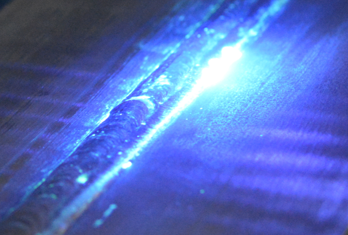
Figure 2: Penetrant Testing
Penetrant testing is the most common technique for detecting ClSCC in stainless steel pipes. PT involves applying a dye to the surface of the pipe and then wiping it away, leaving the dye in any cracks or defects that may be present. While PT is effective at detecting surface-level defects, it cannot detect defects on the far-side of the pipe or inside the pipe wall.
It is generally accepted that penetrant testing has the following advantages:
- Sensitive to small surface discontinuities
- Few material limitations: works on metallic, non-metallic, magnetic, non-magnetic, conductive, and non-conductive materials
- Works on complex geometric shapes
- Visual, real-world results
- Liquid penetrant testing equipment is highly portable
- Liquid penetrant testing equipment is individually very affordable
However, PT also comes with substantial disadvantages:
- Only sensitive to surface-breaking defects
- Extensive and time-consuming pre-cleaning is necessary as critical surface contaminants can mask defects
- Only works on relatively non-porous surface materials
- Direct access to the surface under test is required
- Multi-process testing procedure
- No quantitative depth sizing
- No recordable data available for progress monitoring
- Time-consuming post-cleaning also necessary
- Environmental concerns, PT may require costly handling and disposing of chemicals
- User dependent
Eddy Current Testing for CSCC
Eddy current testing (ECT) and eddy current array (ECA) are more advanced techniques that can detect ClSCC with greater accuracy and precision than PT, and can save a considerable amount of time and money. ECT systems have a higher initial cost, but do not require consumable chemicals, have little to no surface preparation, and are faster than liquid penetrant inspection in typical applications, despite being user dependent.
Eddy current array testing improves on the ECT technology by using multiplexed arrays of coils arranged in rows (instead of one or two coils), which allows covering a larger area in a single scan pass.
The advantages of ECA over ECT are obvious:
- The wider coverage leads to significantly faster scans
- The larger ECA probes considerably lower the operator dependency, and offer better data than manual raster scans
- ECA offers better detection capabilities, as well as accurate defect positioning because the inspection data can be encoded, and, perhaps most importantly, offers sizing capabilities
- ECA does not require the use of chemicals or dyes, making it a safer and more environmentally friendly option
- The simpler ECA scan patterns make analysis markedly simpler, faster, and beyond doubt
- Data can be recorded, making defect progress monitoring possible
Far-Side Detection with ECA
The main advantage of ECA over PT regarding CSCC is its ability to detect far-side defects. These defects are located on the opposite side of the pipe wall from where the ECA probe is placed. Using low-frequency coils in the long single driver topology, it is possible to reach through a thickness equal to approximately one coil diameter.
 Figure 3: ECA probes can detect far-side volumetric defects down to 20% wall loss when the wall thickness (WT) is equal to approximately one coil diameter (OD).
ECA Probe and Instrument Selection
Eddyfi Technologies manufactures a low-frequency version of its popular and Spyne™ probes to allow far-side detection of corrosion and cracks in non-ferrous materials like stainless steel or aluminum.
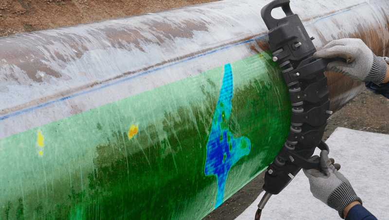
Figure 4: Spyne low-frequency probe for far-side inspection
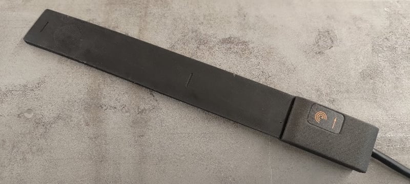
Figure 5: I-Flex low-frequency probe for far-side detection
In a 6-millimeter (0.23-inch) thick aluminum plate, it’s possible to scan from the opposite surface and detect flat bottom holes as shallow as 1.2 millimeters (0.047 inches) (20%).
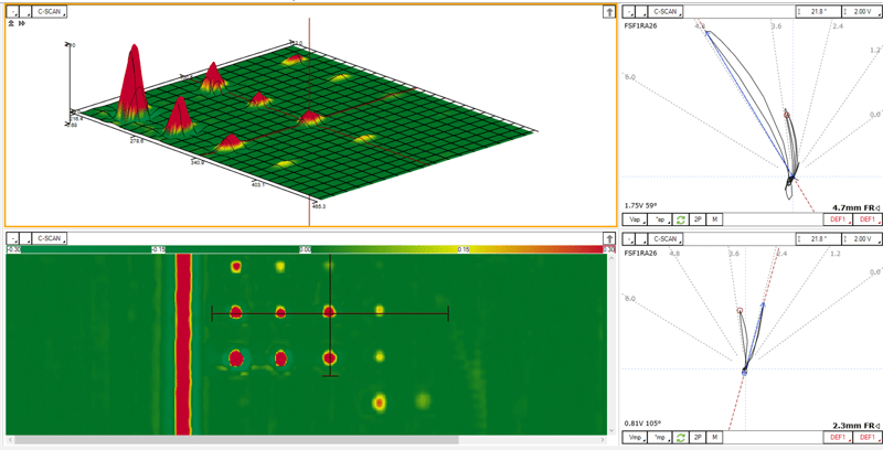
Figure 6: The I-Flex XL scanning an SS316 plate with manufactured flat bottom holes on the far side of the wall


Figure 7: Reddy® surface ECA instrument (left) Ectane® 3 (right) for eddy current array surface inspections
Compatible with the Ectane 3 or the incredibly portable Reddy Surface ECA, inspectors can easily perform inspections across a wide array of industries and locations, while the Magnifi® acquisition and analysis software captures high-quality repeatable data.
A real-world example
In a SS316 pipe with WT of approximately 6 millimeters (0.23 inches), internal corrosion can be detected at an early stage before they act as nucleation sites for SCC.
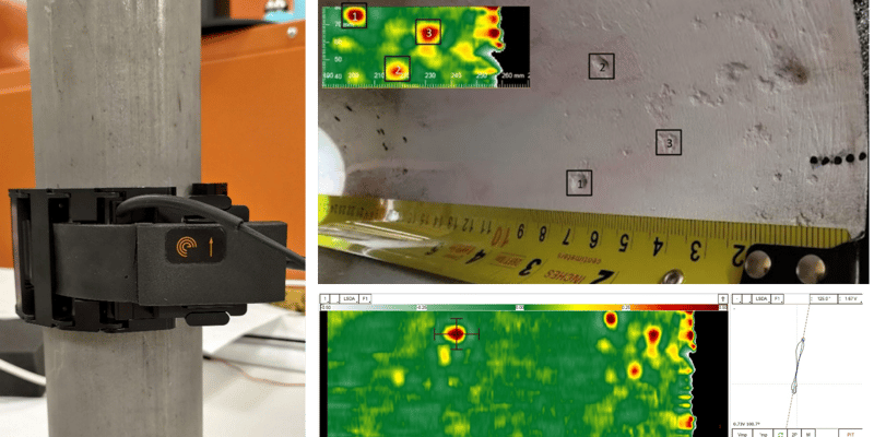
Figure 8: I-Flex with manual pipe scanner, scanning the pipe from the outside. Notice the C-scan is a mirror image of the inside wall since we are seeing through it.
Overall, while penetrant testing is a common and effective technique for detecting external CSCC and corrosion in stainless steel pipes, ECA offers significant advantages in terms of accuracy, precision, speed, and the ability to detect far-side defects. As industries continue to prioritize safety and efficiency, it is likely that ECA will gain increasing popularity for detecting and preventing ClSCC in stainless steel pipes.
Want to dive deeper into Eddy Current Technologies for critical applications? Watch our exclusive webinar featuring Technical Sales Specialist Larbi Halal for expert insights and real-world examples.
For more information on how ECA can take your inspection a step above the rest, check out the Eddyfi Academy course on ECA surface inspection, explore pricing on the eStore or contact us; our team is ready to answer all of your NDT questions.