
The preferred NDT technology for complex composites inspection is phased array ultrasonic testing (PAUT). A combination of dedicated probe configurations, a high-performance PAUT system, and advanced software that includes specific tools and algorithms is necessary for fast and reliable inspections. Standard phased array UT inspection requires precise alignment between the probe and the specimen. In the case of complex geometries, this typically involves comprehensive and therefore expensive systems, and precise knowledge of the specimen geometry. Recently, the Time Reversal technique —a real-time adaptive process— has been implemented for rapid and reliable phased array UT inspections on these complex geometries.
Here's the problem
Composite structures are being used more and more in aircraft. This includes the fuselage and different parts of the wings, the skin, stringers, and spars. All these components have different shapes, most of which are complex geometries. Therefore, the examination method must be adaptable to these challenging conditions.
-1.png?width=600&name=MicrosoftTeams-image%20(15)-1.png) Figure 1 Example of aircraft composition
Figure 1 Example of aircraft composition
The manufacturing process of composite materials can create different types of defects. Inspection after manufacturing must be able to detect porosities, foreign bodies, and delamination present in the CFRP structures (Figure 2). Another challenging aspect of the examination of aerospace components is inspection speed. The large manufacturing volumes demand high inspection speed in order to reduce cost.


Detection of laminations in composite stringers Detection of laminations in composite spars
Figure 2 Examples of components and potential defects
We present the Beyond Current solution
In order to overcome the challenges listed above, Eddyfi Technologies offers an efficient solution for composite material inspection. This solution is based on dedicated 1D linear array PAUT probes, advanced PAUT hardware, and a complete inspection software package including innovative features. The Zetec solution can be integrated to the customer’s manipulator.
Phased Array UT Probes
To optimize the detection capability, the probe selection must be made carefully and according to the specimen geometry. Most inspections are performed essentially at normal incidence with the component surface. For typical composite shapes, this normally requires a combination of two types of probes. A linear 1D phased array probe is used to inspect flat surfaces, as seen in Figure 3. These probes typically have 32, 64, or 128 elements.
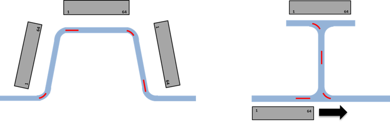
Figure 3 Inspection of straight sections using linear 1D probes
For curved sections, arc-shaped 1D probes are used, typically with 32 or 64 elements (Figure 4).
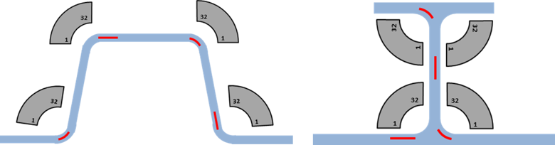
Figure 4 Inspection of convex and concave surfaces using arc-shaped 1D probes
UltraVision Software
UltraVision - Classic software manages inspection technique development, UT data acquisition, displays real-time images of the data, and provides advanced data analysis and reporting tools. It handles a multitude of phased array UT applications for various industries. The Iterative Time Reversal technique is included in the toolkit offered in UltraVision.
Time Reversal Concept
Time Reversal is a real-time adaptive UT inspection technique designed to eliminate the effects of misalignment between the probe and the specimen. This is achieved by using “surface profiling”; this process uses the time of flight from individual elements of the probe to characterize the surface of the inspected specimen. Once “surface profiling” is complete, a compensation delay is applied to the individual elements of the probe, and essentially normal incidence of the beam on the surface is achieved.
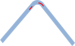
The two-step process starts with “surface profiling” where a plane wave is generated by firing all elements simultaneously. When the wave meets the specimen, it is reflected back to the probe where it is received. The reflected wave is no longer a plane wave, it is affected by the shape of the inspected component. The variation in the wave shape translates into a different time of flight for the response on each individual element i (see Figure 5).
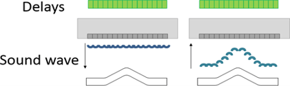
Using the different time of flights measured in the initial firing, the software calculates the delay for every individual element i that will compensate the differences introduced by the surface profile. Equations (1) and (2) show how the corresponding emission and reception delays are calculated where ti is the time of flight for the wave received by element i. This process can be repeated numerous times until the wave reflected from the surface back to the probe is a plane wave (see Figure 6).
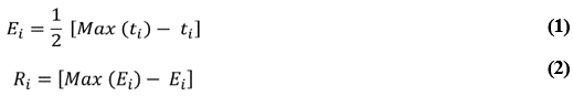
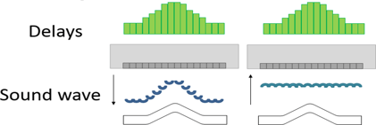
Figure 6 Application of delays to fit the surface profile
The second step of the Time Reversal technique is recording data using the delays obtained during the profiling phase. Data acquisition is performed using electronic linear scanning with a limited active aperture (e.g., 8 elements). Figure 7 shows the principle (left) and shows real inspection data (right). At each scan position, both steps are performed in real-time to maintain valid examination and accurate data, even on varying surface geometry.
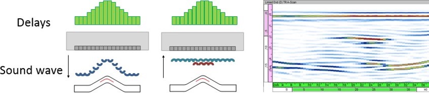
Figure 7 Data recording using compensated delays
This complete process is performed in real-time and allows scanning speeds similar to standard phased array UT when using similar focal law groups and equivalent UT settings.
Advanced PAUT System
Eddyfi Technologies offers various phased array UT systems supporting the Iterative Time Reversal technique; ZIRCON®, QuartZ® and TOPAZ32®. All systems are battery operated and are 32/128 configurations. The active aperture of up to 32 elements and the possibility to connect up to 128 probe elements allow the system to adapt to various inspection conditions. In addition, multiple units can be connected to the same computer to control the complete set of probes from a single station (Figure 8).
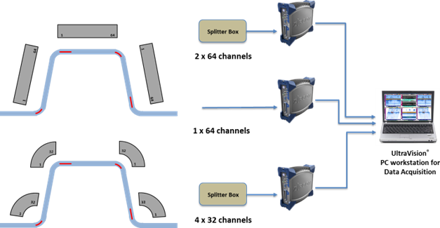
Figure 8 Example of a complete Time Reversal inspection solution for a typical stringer geometry
Case Study
A CFRP sample was manufactured by an industrial composite provider (see Figure 9) to demonstrate the capabilities of the Time Reversal technique. It has typical composite material attenuation and contains multiple artificial brass inserts to simulate typical defects. The inserts are 3 by 10 millimeters (0.11 by 0.39 inches) and 30 by 10 millimeters (1.18 by 0.39 inches), located at various locations and depths throughout the sample.
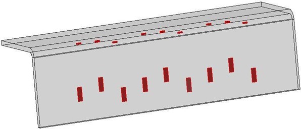
Figure 9 CFRP sample
This type of geometry can be inspected in three scan lines, requiring two different probes. The flat sections are examined using linear 1D probes, and the curved section is inspected using an arc-shaped 1D probe. All inspections are performed in complete immersion.
Flat Section
For the flat sections, an LM 5MHz probe was used. It has 64 elements, a pitch of 0.6 millimeters (0.02 inches) and a width of 10 millimeters (0.39 inches). An aperture of 8 elements was used. Scanning was performed manually, while attempting to maintain optimal probe alignment and orientation. Theoretically, there should be no major difference between the Time Reversal data and the standard phased array UT data. However, different results are shown on the amplitude C-Scans of Figure 10. Even when the operator tries to maintain optimal conditions, the backwall amplitude on the standard PAUT data is extremely sensitive; indeed, a slight misalignment or variation in the water column can cause a loss of backwall amplitude. A constant backwall amplitude is important for porosity detection. On the other hand, the Time Reversal data shows a constant backwall amplitude over the full extent of the specimen.
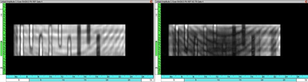
Figure 10 Amplitude C-Scan of the flat section: Time Reversal (left); Standard PA (right)
Curved Section
The curved section of the specimen was inspected with an arc-shaped 1D probe, at 3.5 MHz, with 64 elements. The probe has a pitch of 0.65 millimeters (0.02 inches) and its width is 8 millimeters (0.31 inches). An active aperture of 8 elements was used again. At first the probe was installed on a two-axis mechanical system to ensure optimal orientation and alignment. The probe was then intentionally moved by approximately 3 millimeters (0.11 inches) to demonstrate the capability of the Time Reversal technique to compensate for the misalignment (Figure 11).
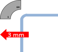
Figure 11 Probe misalignment
Figure 12 shows that the Time Reversal data displays excellent detection capability throughout the entire scan line with all nine defects appearing clearly on the C-Scan. The standard PAUT data does not allow for adequate detection of all flaws in the sample.
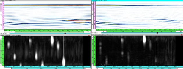
Figure 12 Amplitude C-Scan and End View for misaligned arc-shaped 1D probe. Time Reversal data (left); Standard PAUT data (right)
For the second experiment, the probe was aligned correctly with the specimen, and then the incidence angle of the probe was modified by rotating the probe holder.
Figure 13 Probe rotation
With the orientation of the probe modified, the standard PAUT data becomes completely useless: the UT data of Figure 14 (right) shows that no valid signals are received by the probe. In similar circumstances and during the same inspection sequence, the Time Reversal technique has compensated for the misorientation, and has generated the data shown in Figure 14 (left) that allows for adequate detection of the composite defects.
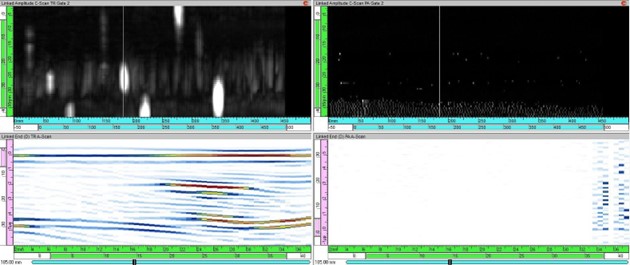
Figure 14 Amplitude C-Scan and End View for misoriented arc-shaped 1D probe. Time Reversal data (left), Standard PA data (right)
Conclusion
The Time Reversal technique for composite structures inspection offers real benefits for the aerospace industry. It compensates for probe misalignment and misorientation in real time without slowing down scanning speed significantly. The Time Reversal technique enhances the flaw detection capability and improves porosity assessment by stabilizing the amplitude of the backwall. By mitigating the need for exact alignment and orientation, the proposed Time Reversal solution reduces the cost of the required mechanical scanning systems, thus bringing additional cost efficiencies for the end customer.
The Time Reversal technique is available as an option on Eddyfi Technologies’ standard PAUT solutions; multiple hardware units can be connected and driven from a single PC, allowing parallel firing of multiple probes, thus offering the potential for a substantial increase of the scanning speed.
If you’re faced with the challenges of performing reliable inspection of complex composite structures, ask us how we can help simplify the process and keep you Beyond Current.