High temperature hydrogen attack happens in an environment where high temperatures and the presence of hydrogen are combined, mostly to low alloy steels. The high temperature causes some of the hydrogen to change into its atomic form which allows it to migrate into the steel. Inside the steel, the hydrogen will react with carbon and form methane which cannot migrate through the steel. Therefore, it gets trapped in the metal, typically as microscopic methane bubbles at the grain boundaries in the steel (stage 1). As these bubble start to grow, they start to coalesce (stage 2) and eventually lead to fissuring and cracking (stage 3). HTHA occurs preferentially in welds, heat effected zones, and in material that received no heat treatment.
As a result, HTHA may express itself in various shapes including decarburization and small voids in the early stages, linked voids at intermediate stages, and blisters and crack-like damage in the late stages. Due to the variation in defect shapes and the small size of early damage, HTHA is a challenging ultrasonic examination task. Until recently, API RP 941 recommended a number of manual ultrasonic techniques that were developed in the 1980s and 1990s such as Advanced Ultrasonic Backscatter Technique (AUBT). The 2020 update to API RP 941 now includes more recent techniques such as time-of-flight-diffraction, phased array ultrasonic testing, and total focusing method. We should also mention the TULA probes which are essentially Ultra Low Angle TOFD, or TULA, probes. All these news tools are available with the Capture™ software embedded on the Cypher® and Mantis™ flaw detectors by Eddyfi Technologies.
Given the properties of early HTHA damage being a small void in the material, it is important that the inspection technique is sensitive to small defects, while also able to cover the potentially affected area efficiently. For correct characterization, it is also helpful that the technique has a high resolution to distinguish the anomalies from other reflectors. The following table shows an overview of the five techniques with their main advantages and disadvantages.

TFM with New Probe for HTHA
FMC/TFM was recently added to the ASME Boiler and Pressure Vessel Code and successfully used for the inspection of HTHA. A paper from BP co-authored with Eddyfi Technologies, Assessment of High-Temperature Hydrogen Attack Using Advanced Ultrasonic Array Techniques, was published November 2020 in Materials Evaluation, receiving the 2021 Outstanding Paper Recognition from the American Society for Nondestructive Testing (ASNT).
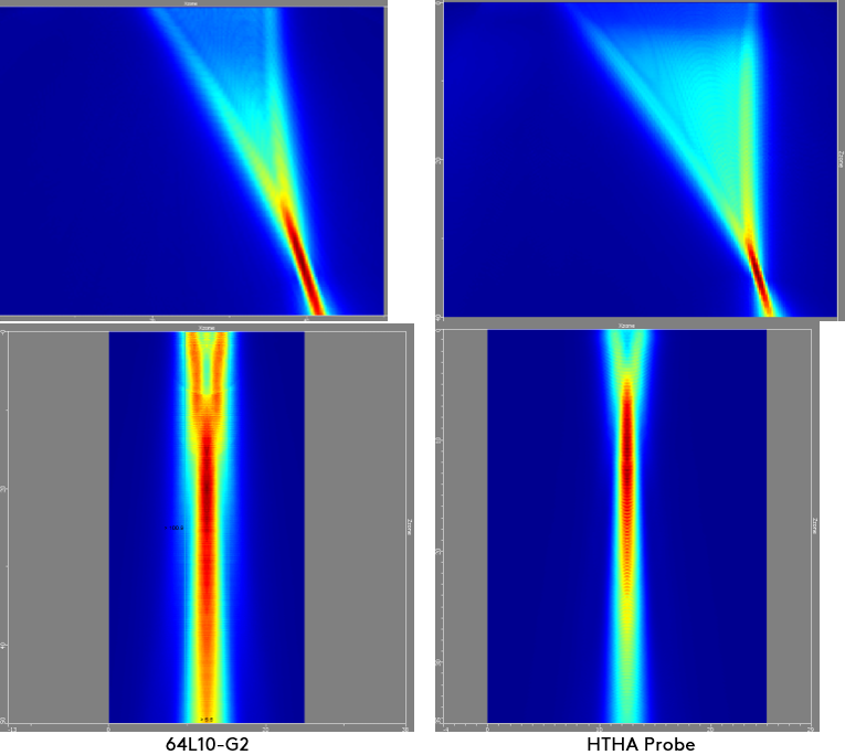
As FMC/TFM focuses everywhere within a region of interest, it offers optimum spatial resolution along the active plane which is vital for the detection of small defects such as HTHA. It is however still important to optimize the probe parameters (pitch, frequency, wedge, etc.) to minimize this spatial resolution while avoiding grating lobes. We have developed a new PAUT probe for the inspection of four 35-millimeter (mm) [1.4-inch(in)] samples, which improves sensitivity over standard PAUT probes. In the following images, we show the beam spot along the active and passive plane, comparing a 64L10-G2 probe (10 MHz, 64-element, 0.35mm/ 0.01in pitch, 8mm/0.3in elevation) with an L0 wedge to our new probe also with 10 MHz and 64 elements with both L0 and SW55 wedges.
Frequencies used in these calculations are the ones measured experimentally. For the active plane, we look at the worst case scenario which is one of the pixels located at the extreme bottom corner.
For the active plane, we can see that both beams are quite similar. There is a slight improvement with the new probe going from a 1 to 0.8 millimeter (0.039 to 0.031 inch) focal spot.
For the passive plane, we can see that the beam for the special probe is between one half and one third of the beam from the standard probe. This improvement in spatial resolution offers better sensitivity to detection as the surface of the focal spot is 2.5 times smaller at its smallest point compared to the standard probe. It also provides better characterization of defect coalescence.
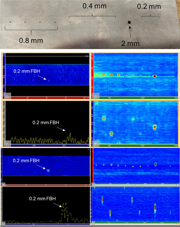
To illustrate the improvement in sensitivity, we perform an inspection on a 10-millimeter (0.4-inch) thick mockup containing Flat Bottomed Holes (FBH) ranging from 2 millimeters (0.08 inches) down to 0.2 millimeters (0.008 inches) located at different depths. In the following figures, we show the back of the sample with the various holes and the results obtained with the standard probe at the top and the HTHA probe at the bottom. The T-scan and A-scan are displayed for one of the 0.2-millimeter (0.008 inches) FBH. The standard probe has a hard time detecting the 0.2-millimeter (0.008 inches) FBH while the HTHA probe detects them with a Signal-to-Noise Ratio (SNR) of 14 dB. Due to the larger beam along the passive plane for the standard probe, defects appear elongated along the horizontal axe making it more difficult to distinguish between close indications.
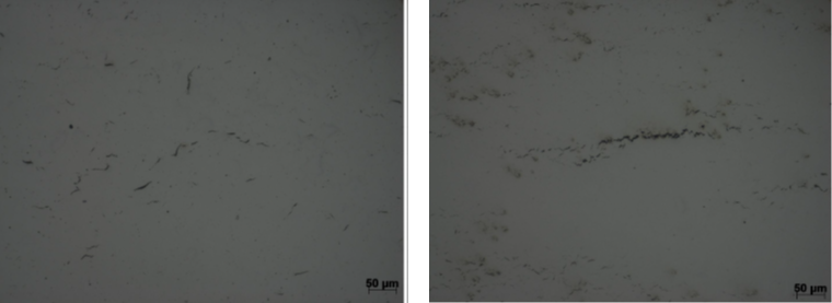
The HTHA sample that we looked at is a 150x45x25-millimeter (5.9x1.8x1-inch) block that contains manufactured HTHA. The test specimen was sectioned to expose HTHA cracks near the block surface. The specimen was metallographically ground and polished using procedures given in Practice ASTM E3-01 (2007) Standard Guide for Preparation of Metallographic Specimens. The following images show HTHA damage along one of the surfaces. One can see that defects are in the dozens-of-microns range while larger defects (~200-300 µm) appear (right image).
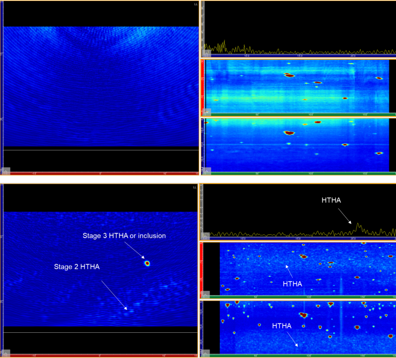
The sample was ultrasonically scanned using the FMC with the special probe and a one-axis encoder. The TFM area is 30x20 millimeters (1.2x0.8 inches) with 90kpixels leading to a pixel size of 0.09 millimeters (0.004 inches) to respect the Amplitude Fidelity described in Standards. When data is collected every millimeter, the scanning speed is 54 millimeters (2.1 inches) per second.
The following images show the results obtained with the standard probe (top) and the HTHA probe (bottom). The images display a T-scan (left) and A-scan, C-scan, and Sideview (right). The large features are visible with both probes; it is not clear at this point if they are inclusions or stage 3 HTHA for which microcracks have coalesced to form larger cracks as shown in the previous macrography image (right). It is not possible to clearly see the stage 2 HTHA with the standard probe, while it is clearly visible with the new HTHA probe.
We evaluated the same probe on the same sample using an SW55 wedge. Shear waves are typically used to look for HTHA in the Heat Affected Zone (HAZ) or the weld. Here, we used it to inspect the base material. The idea here is to minimize the dead zone and isochrones that are sometimes seen when using TFM with an L0 inspection. We use a 25x28-millimeter (0.98x1.10-inch) ROI with 219 kpixels. Despite the increase in pixel count, the scanning speed is 76 millimeters (3 inches) per second due to Plane Wave Imaging (PWI). This could be further improved by using the envelope of the TFM signal.
As sensitivity is key here, we use the PWI acquisition scheme with TFM (learn more in this blog). PWI is essentially a sectorial scan using the full aperture of the array (64 elements here) combined with TFM reconstruction. The advantage is a gain in productivity as we use less angles compared to FMC, and more sensitivity as we fire all the elements rather than one at a time. One can obtain more sensitivity by using more angles but with reduced scanning speed. PWI is covered by the codes.
We calculated a Time-Corrected Gain (TCG) following the sensitivity correction described in ISO 23865 and as implemented in Capture software (learn more here). This is essential when performing HTHA inspection as operators want to have the same response wherever the HTHA is located in the ROI.
The following image shows the results obtained with the new HTHA probe. As before, we display a T-scan, A-scan, C-scan, and Sideview. One can see on the A-scan that the difference in amplitude between the base material (beginning of the A-scan up to 17 millimeters/0.7 inches) and the HTHA region is pretty big. We measure a 20 dB difference with the larger indications along the backwall. This difference is larger than the results obtained with a L0 wedge. This can be attributed to the smaller wavelength of the shear wave and the higher energy input of PWI.
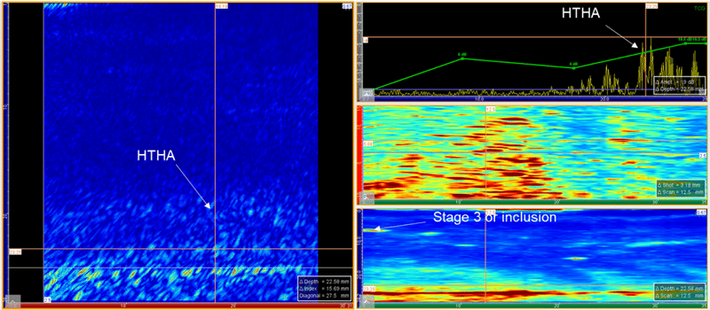
The following video shows the results as we move along the scan axis. One can see pretty easily the area of the sample that contains HTHA.
When it comes to HTHA inspection, one must look for PAUT equipment that offers all the techniques recommended by API (UT, TOFD, PAUT, TFM), but also the the right probes and inspection configuration. Eddyfi Technologies has designed a new PAUT probe with better sensitivity and combined with PWI and TCG, we obtain higher sensitivity and better scanning speed than traditional and dual-linear array probes.
For surface inspection and detection of small cracks, our Eddy Current Array (ECA) solutions are well suited. Eddyfi Technologies ECA probes can be tailored to your application to provide quantitative and repeatable measurement, extracting length and depth information. Check out this application note on ECA in reformer tubes enabling the evolution from time-based to condition-based assessments. Moreover, the Alternating Current Field Measurement, or ACFM®, technique has a proven history of conducting high temperature inspections for surface-breaking cracks; learn more here. We invite you to contact us and discover the Beyond Current solution(s) for better HTHA inspection and so much more today!


