Total Focusing Method (TFM) is known to generate high-resolution detailed images that are easy to interpret and less sensitive to misalignment or positioning errors than standard phased array ultrasonic testing (PAUT). Like any ultrasonic technique, TFM requires calibration before inspection to ensure repeatable and reliable data.
You’ve probably seen Total Focusing Method when researching advanced phased array UT tools. Developments in Non-Destructive Testing (NDT) technology have resulted in an increase of TFM enabled devices now commercially available. TFM algorithms create an image by focusing energy at every pixel of a Region-Of-Interest (ROI). While TFM offers optimal spatial resolution across the ROI, image intensity isn’t naturally uniform across the grid due to variations of acoustic pressure and material attenuation. Like any UT technique, a Time Corrected Gain (TCG) calibration is required to ensure that indications have uniform amplitude with depth and position.
For PAUT, standards require that all individual beams used must be calibrated to provide distance measurement and amplitude correction over the sound path employed in the examination. While TFM doesn’t exactly create beams, each pixel is the result of a “delay law” applied to an array probe to focus the acoustic energy at that point. Amplitude calibration for TFM requires having the same sensitivity for every pixel in the ROI.
M2M Gekko® and Mantis™ ultrasonic flaw detectors feature Capture™ software which offers advanced TCG, making it easy and quick for operators to perform amplitude calibration for their inspections.
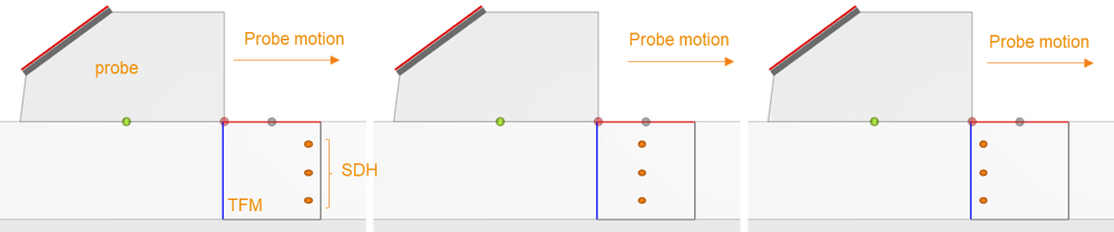
TCG is done using a calibration block with a series of identical side-drilled holes (SDH) at different depths. The amplitude of each SDH is recorded for each pixel along a horizontal line, over the complete width of the ROI, by moving the probe over the SDHs as shown in the following figure.
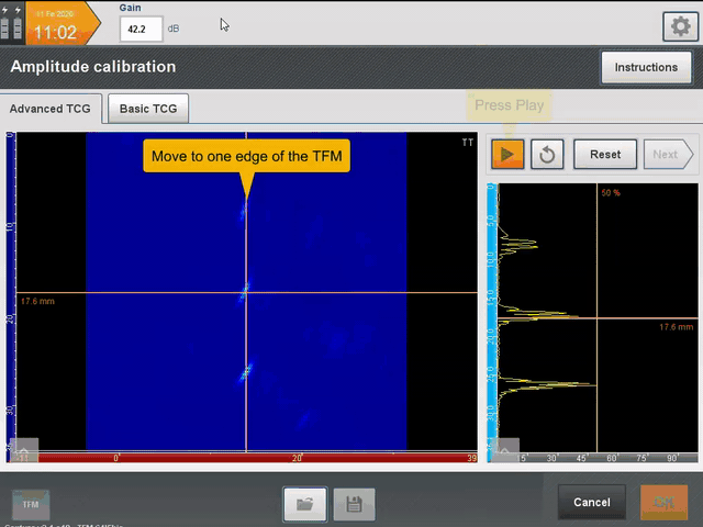
As the transducer moves, a persistence image is generated by retaining the maximum pixel amplitude for each pixel. For each vertical line in the ROI, an amplitude value is now available for each of the SDHs. A depth correction is then performed by determining the gain necessary to adjust the response of each SDH to the desired level, typically 80% screen height. The TCG process is summarized in the following video.
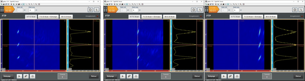
At the end of the TCG calibration, all pixels have the same amplitude, regardless of their position in the ROI. The following image shows TFM images of three SDH obtained for different mechanical positions. The echodynamic curves project the maxima of each row along the depth axis, allowing one to directly see the peak amplitude of the SDH. We can check that the amplitude of the three SDH is exactly the same for all positions.
This TCG calibration tool is available for standard PAUT, FMC/TFM and also for the new Plane Wave Imaging (PWI)/TFM feature introduced with Capture 3.1.
Download this guide on the seven questions you should ask when choosing your next phased array UT solution. Interested in learning more about the Total Focusing Method? Check out our webinar on how life is better with TFM. Finally, we’ve got a team of global experts that would love to answer your specific questions; get in touch today!