Eddyfi Technologies leverages its worldwide centers of excellence to propose a complete ecosystem for people performing corrosion mapping inspections. Scanners developed by Silverwing (manual R-Scan Array, semi-automated LYNCS™, and fully automated RMS PA) work smoothly with our world famous phased array ultrasonic testing (PAUT) systems, Mantis™ and Gekko®. Aqualock is the universal probe among the scanners and is based on a water box concept that makes it easier to scan components with bad surface conditions. The ultrasound propagates through a column of water eliminating the need for a wedge, thus providing the benefits of improved signal consistency, accuracy, and limited dead zone. Using a water box concept requires the proper tools to obtain the correct wall thickness measurements.
Second Backwall Echo Synchronization
When dealing with a water box concept, there are slight variations in water column height due to compression of the hard foam used at the front of the water box. When performing corrosion mapping, operators want to measure the remaining thickness of the component and not variations in the water column. It is thus necessary to use synchronized gates that measure the differences in time-of-flight between the backwall and the front surface echo.
If the asset is coated or painted, we want to measure the remaining wall thickness and not the sum of the coating/paint with the remaining thickness. For these configurations, a second gate positioned along the second backwall is typically used. C-scans and remaining thickness indicators are then displayed as the second backwall minus the first backwall. The difference between the first backwall echo and the second backwall echo, both synchronized with the front surface echo, removes the influence of the coating/paint in the remaining thickness measurement.
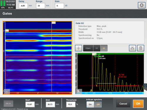
For extreme corrosion, the remaining wall thickness can be really small leading to backwall echoes really close to each other which makes it difficult for the second gate to capture the second backwall echo. The following images show the two gates set for a 12.5-millimeter (0.5-inch) thick component (left). The first gate (white) starts as close as possible to the interface echo; the second one start as close as possible to the first gate. In the image on the right, the remaining thickness is only 2.5 millimeters (0.1 inches); while the first gate correctly captures the first backwall echo, the beginning of the second gate is not early enough to capture the second backwall echoes. While it should be possible to adjust the second gate to capture that backwall echo, this could lead in measuring the first backwall echo in areas where there is no corrosion.
 |
 |
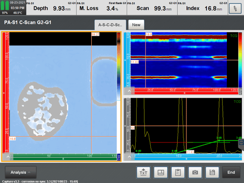
The tool is illustrated on a corrosion plate using two gates (first and second backwall echoes) with a first flank threshold. A Time Corrected Gain (TCG) amplitude was applied on a corrosion-free part of the sample to have the first and second backwall echoes with 80% screen height response. The image on the left shows a C-scan with a difference between the first and second backwall echoes both synchronized on the interface echo. We can see that a lot of data in grey indicating thickness measurement was not possible for these positions, probably due to one of the echoes being smaller than a gate threshold. Plus, the remaining thickness measured within the corrosion gives wrong indications due to the fact that the second backwall echo is not contained within the second gate due to too much material loss. The image in the right is using a second backwall synchronized on the first one; we can see that a lot of areas are not measured.
 |
 |
Floating Gates
We saw in the previous image (right) that heavy corrosion can lead to a drop in amplitude of the first and/or second backwall echo making remaining thickness measurement more difficult. Lowering the threshold of the gates to detect weaker echoes can lead to measuring the wrong echoes.
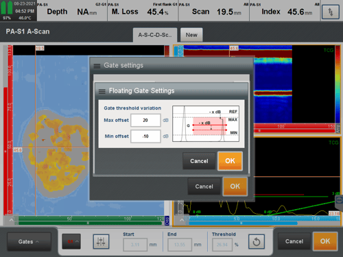
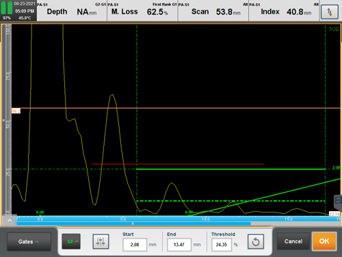
To overcome this problem, Capture 3.3 introduces a new feature called floating gates. Instead of having one threshold value, a floating gate adds two thresholds. The following image on the left shows the setup for one example; the operator decides upon two offsets: a minimum and a maximum which are based on the initial threshold of the gate. The image on the right shows the second backwall gate (green) with the initial threshold at 20% (continuous line) and the minimum offset 10 dB lower (dotted line). The second backwall echo doesn’t cross the initial threshold but it crosses the minimum offset allowing measurement of this echo.
 |
 |
If the echo crosses the initial threshold, then the minimum offset is not used, and the echo measurement is based on the initial threshold.
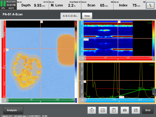
We applied the floating gate feature to the previous example using a minimum offset of -10 dB on both the first and second backwall echoes. We can see that a lot of the grey pixels observed before are not measured.
![]()
Floating gates ensure that the remaining thickness reading isn’t affected by reduction of an echo amplitude due to sound attenuation.
Capture 3.3, the second major software release in 2021, offers additional tools for corrosion mapping inspections particularly for coated/painted assets and assets with massive corrosion. The PAUT technique is one of the techniques at Eddyfi Technologies designed to tackle corrosion mapping inspections. The Pipescan HD, Lyft®, and remote visual inspection tools are other solutions that can be used to address various corrosion problems.
For more information on Capture software and our advanced phased array ultrasonic testing and total focusing method instrument offering, contact our experts today!