
As with any introduction of new inspection technology, it is important to validate performance in a controlled environment. This introduction required the procurement of a spiral welded sample with artificially manufactured corrosion defects. A combination of the Pipescan™ HD and LYNCS CM systems were put to the test to demonstrate the benefit of using a combined solution to maximize productivity and provide quantitative results of damaged areas. The Pipescan HD was used to rapidly screen the majority of pipe walls and identify areas with a pre-determined reporting threshold, 30% material loss in this case. The Immersion type phased array corrosion mapping system was then used to measure the depth of indications. Where physical restrictions with dead zones or areas where neither tool could be used —approximately 100 millimeters (4 inches) on either side of the spiral weld— manual scanning was performed using a 7.5MHz 64 element phased array ultrasonic testing (PAUT) probe and zero degree wedge for both detection and characterization of defects. The sample was 16 mm (0.6 in) nominal wall thickness. Although the Pipescan HD works on a range of thicknesses, as with all non-destructive testing (NDT) methods, there are optimal conditions for performance. To balance detectability with ergonomic performance, the magnetic strength was designed to saturate 12.7 mm (0.5 in) wall thickness to detect wall thinning as discreet as 10%. It should be noted that thicker material can also be inspected but the defect would need to be larger for detection. With this in consideration, it emphasizes the benefits of using a supplementary technology such as PAUT. This combination of advanced techniques resulted in a highly efficient inspection with precise data collected in particular areas, increasing productivity while maintaining a high probability of detection (PoD). Check out the results for yourself!
Pipe Sample Details
- Material: Carbon Steel
- Nominal Thickness: 16.0 mm/0.6 in
- Outer Diameter: 915 mm/36 in
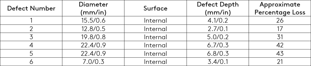
- 6 artificial defects drilled internally at different depths
- 4 linear scans (185 mm/7.3 in wide) performed from left side to diagonal weld using Pipescan HD
- 17 vertical scans (60 mm/2.4 in wide) performed also from left diagonal weld using LYNCS CM
- Areas adjacent to the welds were scanned with near wall coverage PA probes
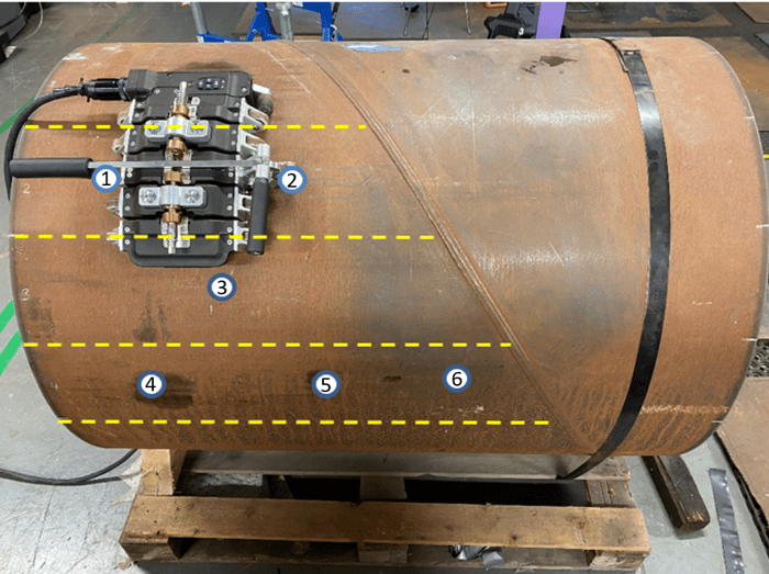
Figure 1: Pipe Sample with Defect Locations
Equipment Used
- MFL Pipescan HD scanning head PS-HD-MFL-127XFLAT and Swift M data acquisition unit
- PAUT LYNCS CM manual encoded system and Mantis™ acquisition unit
- G3 64element 7.5MHz probe and L0-G3 wedge
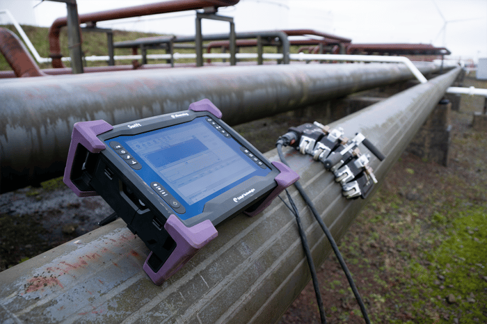
Figure 2: Pipescan HD with Swift M
Setting up the Pipescan HD for inspection is easy thanks to a unique curvature adjustment tool. Using a powerful, permanent magnet to magnetize the material under test, the Pipescan HD employs an array of hall effect sensors that identify magnetic field “leaks” which correlate with areas of wall loss. It is designed to maximize speed, reliability, and confidence in detection of volumetric defects including corrosion and pitting in carbon and low alloy pipework or vessels. All scanned data is automatically recorded, and reports can be issued on the spot to give asset owners immediate visibility on the condition of their assets. The Pipescan HD relies on magnetic saturation of the component which is directly related to the strength of the magnet. Recent advances in magnetic flux leakage (MFL) technology including an increase in magnetic strength, more sensors, and ability to record data has increased PoD of smaller volume defects like Microbially Induced Corrosion (MIC).
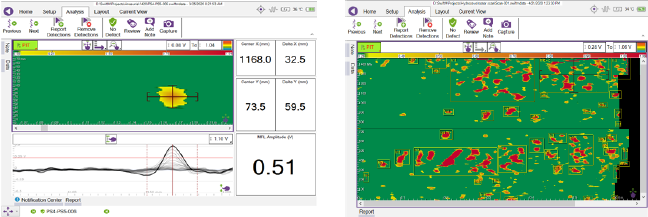
Figure 3: High-Resolution Data Collection Example
Because the MFL technique is sensitive to a volumetric change in material thickness and not specifically defect depth, combining an alternative inspection such as phased array ultrasonic testing helps ensure all indications detected by the Pipescan HD can be properly addressed. Enter the LYNCS CM.
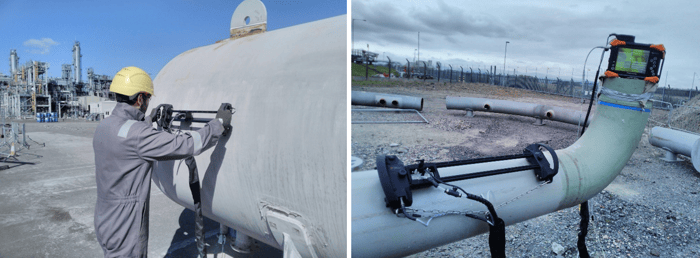
Figure 4: LYNCS CM with Mantis Phased Array Acquisition Unit
This semi-automated scanning system is ideally suited to vessel and pipework inspection. It has an extremely low profile and lightweight design, the integrated encoder and on-board button delivers fast and efficient corrosion mapping of complex geometries, dead zones for automated scanning systems, and pipes as small as 100 mm (4 in). When paired with Eddyfi Technologies' industry-leading PAUT Instruments, this highly portable battery-operated solution is ruggedized for remote work with all data recorded and displayed in multiple views for efficient defect characterization.
Areas adjacent to the spiral weld and dead zones not covered by the Pipescan HD and LYNCS CM were inspected using a small footprint PA probe. A small footprint probe reduces probe rocking and maintains the best quality data collection in these areas. Check out our web store to buy PAUT probes and wedges online.
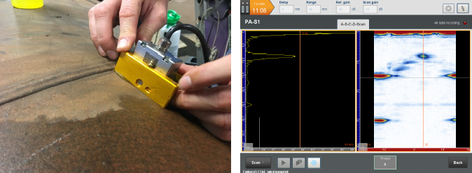
Figure 5: G3 Phased Array Probe and Example of Data Collected from Mantis
Lab Based Trial Results
The combination of MFL and PA corrosion mapping enabled the successful identification of all isolated corrosion defects. Rapid screening by the Pipescan HD helped quickly identify areas of wall loss with the focused areas then scanned using quantifiable phased array technology. With both inspection techniques able to provide a permanent record of the scanned areas, the data sets are correlated for axial and circumferential locations, providing asset owners and integrity engineers with the required information for risk-based assessments.
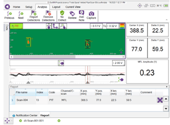
Figure 6: Pipescan HD Data on Simulated Corrosion
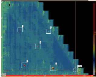
Figure 7: C-scan Display of Phased Array Data Highlighting Detected Defects
Field Trials
Following successful lab-based demonstrations, the next stage of technology qualification and acceptance is confirming that the equipment is also suitable for site conditions. An operational site such as a petrochemical plant presents additional challenges like surface condition, access to the inspection surface, temperature variations, and power supplies. Although efforts are made to ensure machined defects are representative of the expected damage mechanism, it is difficult to exactly replicate the true morphology of in-service corrosion. This combination of factors makes field trials extremely valuable.
Select areas of known corroded spiral welded pipe spools were inspected for these field trials. As with the lab-based trials, the Pipescan HD was used as the primary scanning tool to quickly identify in-service corrosion. With a scanning speed of 1 m (3.3 ft) per second, the typical productivity for this technology is approximately 500 m (1,640 ft) in three hours.
In this example, numerous areas of corrosion were detected with the damage widespread and general as opposed to isolated pitting type defects. Nonetheless, Pipescan HD C-scan images clearly identified the corroded areas for further phased array sizing scans.
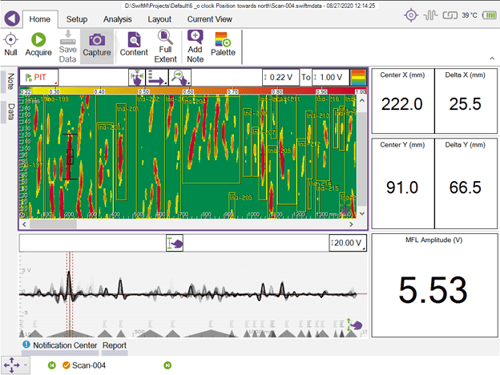
Figure 8: Pipescan HD Data Shows Widespread Corrosion Through the Entire Length of Scan
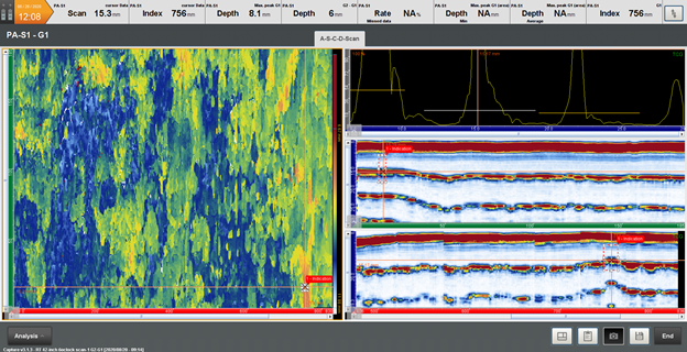
Figure 9: LYNCS-CM Data Provides Quantifiable Data Set with Accurate Remaining Thickness Measurements
Conclusion
There’s no need to let hidden damage mechanisms spiral out of control. For spiral welded pipe inspection, we present two proven instruments with the combined speed and precision of Pipescan HD and the accuracy and high-resolution imagery of phased array corrosion mapping, offering synergistic results that asset owners can use to stay Beyond Current and make decisions with no surprises. Interested in learning more check out the Eddyfi Academy or Get in touch today!