
Accurately measuring the amplitude and the phase angle of a signal is paramount with eddy current. This information is used to calibrate the probe, build the sizing curves, and estimate the depth of the flaws found during an inspection. Even though these measurements can be taken manually with Magnifi® software, many automatic methods are also available and extremely useful for accelerating each step of the inspection process. Depending on the type of signal and what you are looking for in it, one method may be more appropriate than another. Read on to learn more.
Here we used a through wall hole signal from an Eddy Current Array (ECA) DefHi® probe to describe what the Magnifi software does when the following measurement methods are applied:
- Absolute Peak
- Peak-to-Peak
- Peak-to-Peak First Transition
- Average Peak
- Maximum Rate
DefHi Signal
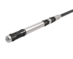
Figure 1: DefHi probe
The DefHi probe includes a bobbin probe with an absolute channel and a differential channel. The signals of a through wall hole acquired with this part of the probe are shown below.
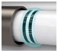
Figure 2: DefHi, Bobbin Part
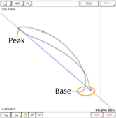
Figure 3: DefHi, Absolute Channel
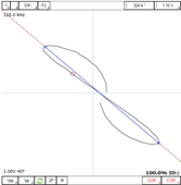
Figure 4: DefHi, Differential Channel
The absolute channel gives one lobe, and the differential channel gives an 8-shaped signal with two lobes.
The DefHi also includes an array of pancake coils that offer a better sensitivity on certain types of flaws and makes the 2D or 3D visualization of the tube possible.
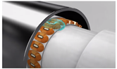
Figure 5: DefHi, Array Part
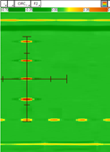
Figure 6: DefHi, 2D C-Scan
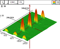
Figure 7: DefHi, 3D C-Scan
The signal of a through wall hole acquired with the array has a single lobe shape that is similar to the absolute channel.
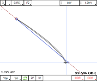
Figure 8: DefHi, Array Channel
Absolute Peak
The absolute peak method is fairly simple. It takes the point where the probe was balanced (0,0) and the point that is furthest from that to make the measurement. The starting point to measure the phase angle is always the Lissajous’s origin. This method can be used to measure an absolute channel that includes one lobe. However, in a tubing inspection, the signal is likely to vary even though no flaw is detected. This is mainly due to the lift-off variation. When this happens, the base of the lobe can be offset relatively to the balanced point. Depending on how the probe was balanced, the origin might also be far from the baseline of the signal. In these situations, the absolute peak method will lead to an incorrect phase angle measurement.
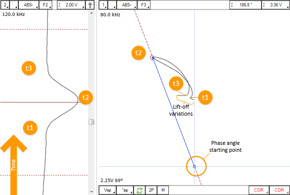
Figure 9: Absolute Peak Method, Absolute Channel, Wrong Angle Measurement
Peak-to-Peak
The peak-to-peak method uses a different approach. The points that are farthest apart in the Lissajous are selected to make the measurement. This has the advantage of being relatively insensitive to the position of the cursors. They can be a little bit larger or narrower and the chosen points will still generally be the same or very close. This method is often used with differential channels because the peaks of their two distinctive lobes are reliable measurement references.
However, point selection is not enough to give a phase angle measurement. The software needs to decide which of the two points is the starting one. The applied rule is simple: the point of origin is the first to have been acquired. This also works well with differential channels. The first lobe comes from the first bobbin that reached the indication. This is repeatable if you can get the distinctive ‘’8’’ shape.
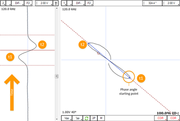
Figure 10: Peak to Peak Method, Differential Channel
Now let’s have a look at the through wall hole signal given by the absolute channel of our DefHi probe (Figure 11). The signal reaches a peak and doesn’t necessarily return to the exact same point at which the lobe started. The maximum distance between two points will be measured between the peak of the lobe and one of the two points at the base of the lobe. The chosen base point will depend on the shape of the signal or on how the cursors were positioned. If the selected base point is the first acquired, like in the image below, the phase angle will be measured correctly (Figure 11). However, if the other point is selected, the phase angle will have a bias of around 180 degrees (Figure 12).
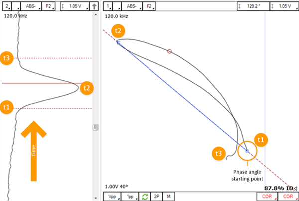
Figure 11: Peak to Peak Method, Absolute Channel, Right Angle Measurement
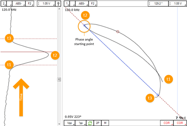
Figure 12: Peak to Peak Method, Absolute Channel, Wrong Angle Measurement
To prevent this from happening, you can select only the portion of the signal that includes the first base point and the peak of the lobe. However, this way of measuring can be restrictive and likely won’t work well if you’re trying to calibrate more than one channel at the same time.
Peak-to-Peak First Transition
The peak-to-peak first transition method uses the same principles as the peak-to-peak to select the measurement points. However, the phase angle starting point is the first one acquired before the peak. This method is proven to be robust and was previously suggested by Magnifi to measure signals that give one lobe like the absolute channel or the channels from the array of the DefHi probe.
Average Peak
Like we’ve seen before, we can expect the base of one lobe signal to move. This generally comes from the lift-off variation to which the array channels are typically sensitive. If this variation is important, the two base points of the lobe will be relatively far away from each other. In this case, selecting one base point or the other to measure the phase angle will influence the readings and will change the estimated depth. Even though the peak-to-peak first transition is a reliable method, choosing the first point to have been acquired before the peak is somehow arbitrary. Therefore, the average peak method uses the average of the two base points as the starting point to measure the phase angle. In the more recent versions of Magnifi, this method is suggested by default for the absolute and the array channels of the DefHi probe.
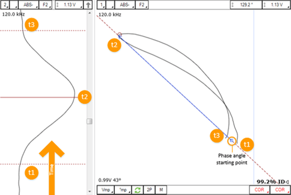
Figure 13: Average Peak Method, Absolute Channel
Maximum Rate
The software allows you to measure the signal amplitude and the phase angle separately. This can be useful with the maximum rate method. This method is only applicable to the phase angle measurement and is often used with differential channels. As its name indicates, it takes the maximum rate of change in the signal. If we refer to the through wall hole given by the differential channel (Figure 14), this maximum rate is located between the peaks when there was a transition between the effect of the first and the second coil.
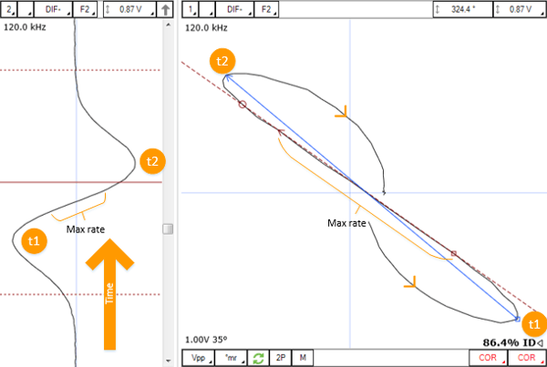
Figure 14: Differential Channel, Max Rate Method
Conclusion
Magnifi offers a wide range of measurement tools that can be selected to automatically measure what is truly important in the signal. The average peak method was developed to give the best phase angle starting point possible on a single lobe signal while the peak-to-peak method, combined with the maximum rate or not, is perfectly adapted for a differential shape signal.
Contact our friendly and knowledgeable team to learn more about leveraging the DefHi probe and Magnifi software for better inspection results and subscribe to our blog to receive email updates and stay Beyond Current.