Without focusing, as the aperture increases, near field increases, beam divergence decreases, and focal beam spot size increases.
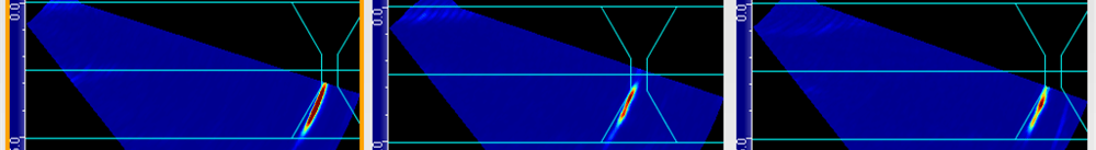
With focusing, as the aperture increases, near field increases, beam divergence increases, and focal spot size decreases, giving us better lateral resolution. This gives us better capability to distinguish between close indications. The following images show the beam profile for a 64L5-G3 probe trying to focus at 50 millimeters (2 inches) using 16, 32, and 64 elements, respectively. One can see that a 16-element aperture is not sufficient to focus at that distance. While both 32 and 64 elements can focus at 50 millimeters (2 inches), a 64-element aperture provides a higher focus [1.6-millimeter (0.06-inch) focal spot versus 3.2-millimeter (0.13-inch)] allowing it to distinguish between the three close porosities.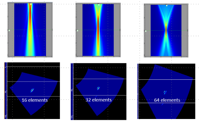
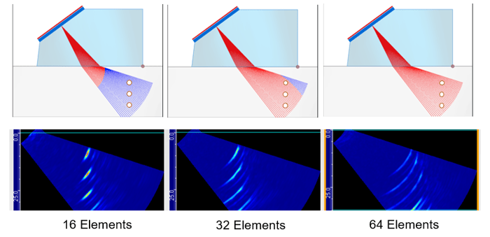
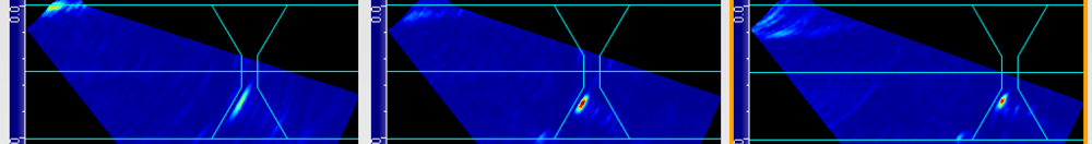
When the reflector is in the near field, it appears distorted. This is due to the fact that interferences in the near field lead to extensive fluctuations of the sound intensity. This is the reason why we try to avoid performing inspections in the near field as it can be extremely difficult to accurately evaluate flaws. Notice in the image below that the Side-Drilled Holes (SDH) start to look distorted when they are located in the red portion of the rays (32- and 64-element apertures). In Capture, the near field information is indicated by the change of color along the rays: red for the near field and blue for the far field.
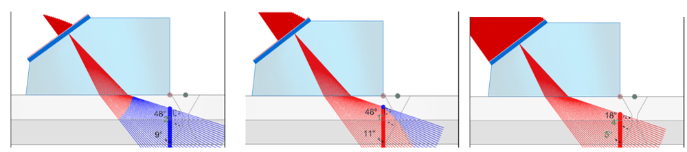
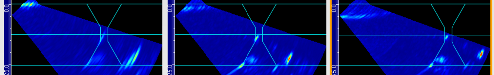
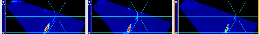
Now, let’s look at the effect of a focusing delay law set to projection aligned with the SDH for different apertures (16, 32, 64). As the aperture increases, the response of the SDHs looks more defined. This is due to a smaller focal spot associated with a higher focusing. The other effect of the tighter focus is an improved sensitivity.
 In the following video, we see the interaction of the beams intersecting SDHs when they’re in the near field and far field, and then we go through the process of focusing the beam. As you can tell there is a drastic difference when focusing.
We look at the impact of aperture for various defects: cluster of porosities, lack of fusion (LOF), toe crack, and slag. We use a focusing delay law set to projection and aligned with the left side of the weld using 16 elements (left), 32 elements (middle) and 64 elements (right) as indicated in the following images. The gain and voltage are kept identical for all images.
The following images are the S-scans obtained for the various defects using 16-, 32-, and 64-element apertures.
Porosities
Lack of Fusion
Toe Crack
Slag
The response of the various defects becomes sharper as the aperture increases. Porosities and slag become more resolved and have a higher amplitude. Diffraction echoes from various facets of the toe crack, especially the tip, are also more resolved allowing for better characterization and thus sizing of the defect.
We saw that focusing when used properly can bring added value in terms of characterization and sensitivity. It is however important to correctly position the points of focalization especially when using a larger aperture. One way to avoid mispositioning those points is to use Total Focusing Method (TFM), which focuses everywhere within a region of interest providing optimum spatial resolution. The following images show the same porosity, LOF, and toe crack with TFM for a position of the probe close to the weld cap.
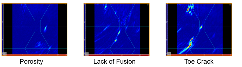
Porosities are resolved properly, tip diffraction from the edges of the LOF and the tip of the toe crack allow proper characterization of the flaw.
Technicians employing either the Cypher with embedded software already know the benefits of the onboard scan plan and focusing parameters found directly on the unit. As demonstrated here, there are key advantages using a larger aperture for powerful focusing. Moreover, TFM allows focusing everywhere in the zone. For certain inspections such as High Temperature Hydrogen Attack (HTHA), a larger aperture is required to detect and resolve smaller flaws. A larger aperture provides smaller beam divergence which provides better lateral resolution and sensitivity. Learn more in this blog on HTHA inspection using TFM.
When performing inspections, it is critical to choose the proper aperture and focusing. We can do this by using a transducer with the correct frequency, quantity of elements, equipment with enough pulsers and receivers. Many times, while performing inspections in the nuclear industry where materials can be thick and attenuative the need for using a large aperture is a requirement. Verifying that the proper PAUT equipment is chosen provides greater capability of inspection capabilities for future inspections and projects. Unsure what solution will best suit your needs? Get in touch with our experts who will be happy to answer any questions you may have.
Eddyfi Technologies truly offers the complete NDT toolbox to address various inspection requirements. Learn more about our customer driven solution packages here, and request a remote demo to see the Beyond Current difference today!