
For a long time it was accepted that eddy currents could not be used to inspect carbon steel, or that very high frequencies were mandatory to clearly identify small flaws in thin wall components. Or, that lift-off needed to be completely absent in order to obtain acceptable results with eddy current.
But times have changed.
The development of high-channel count equipment with advanced electronic and multiplexing capabilities has allowed Eddyfi Technologies to study and better comprehend the behavior of eddy currents in materials, resulting in dedicated coil configurations that optimize readings for many challenging applications.
Besides coil dimensions and drive frequency, one aspect that has a significant impact on a probe’s performance for a specific application is the topology used. Topology, in an Eddy Current Array (ECA) probe, is the specific pattern that coils are physically arranged as well as how they’re wired and multiplexed to generate a desired sensitivity profile for a target defect. There are about five main topologies, each with their own benefits and limitations.
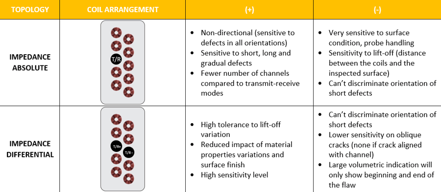
Impedance mode is the simplest, most recognized eddy current topology. It offers a high sensitivity level in cases where lift-off is well controlled. Impedance mode can be divided into two operational modes, Absolute and Differential, each one having different advantages and restraints.
Absolute
In Absolute operation mode, one excited coil generates eddy currents and senses changes in their field: it is its own transmitter and receiver. This mode detects discontinuities in any orientation with a limited number of channels. It is also sensitive to changes in the material properties.
Differential
The Differential operation mode has two excited coils: the signal of one goes into the negative input of the instrument while the other goes into the positive input. When over an area without defects, there is no differential signal between the coils and the background noise signal is very low. When one of the coils pass over a defect and the other is still over good material, a differential signal is generated, allowing the defect to be characterized.
Below is a table of the advantages and limitations of the impedance topology.
The second biggest group of probes are in transmit-receive mode. There are three main topologies in this group: Long Single Driver, Short Single Driver and Short Double Driver. Unlike the impedance topology, transmit-receive topologies automatically imply that a minimum of two coils are used to create an eddy current channel and that each one of them has a different role: one or two being the transmitter(s) and the other being the receiver.
Another specificity is their directionality. When all channel groups are activated, there are a minimum of two groups: one for detection of axial indications (axial to the scan axis) and one for detection of transversal indications (perpendicular to the scan axis). Both groups are sensitive to oblique and volumetric indications. It is possible to activate only one or the other in some applications.
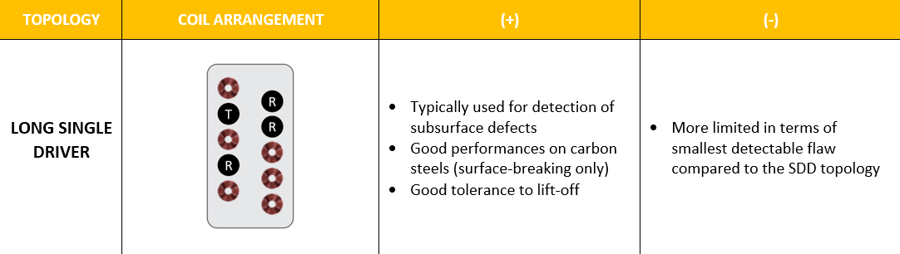
Long Single Driver
In the Long Single Driver topology, the transmitter consists of a single coil. Receivers on the opposite row are for detection of axial indications while the receiver on the same row is for transverse indications.
The driver and receiver are not directly next to each other; they have a distance equivalent to the diameter of one coil. This reduces direct coupling between transmitter and receiver and increases sensitivity over deep flaws without having to lower the frequency as much as when working in impedance, for example.
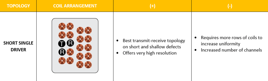
Short Single Driver
The Short Single Driver (SSD) topology is the most sensitive and ideal for small, shallow indications. The signal uniformity and resolution that this pattern offers is by far the best.
But there is another side to the story: the coverage curve of a single channel is very tight. Thus, good resolution and uniformity is obtained using more coils and adding more rows to the probe. The instrument therefore requires a higher number of channels. It’s important to properly weigh the value of this improved sensitivity for a specific application. In some cases, it is optimal but in other applications, the Short Double Driver topology can offer the necessary performance.
The SSD topology consists of a minimum of four rows of coils, as shown below, with the first two being aligned and the second set of two staggered so that it is in between the coils of the first set.
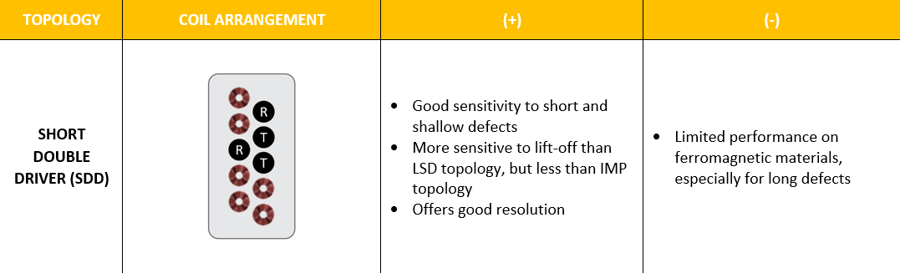
Short Double Driver
Finally, when using pancake coils, the Short Double Driver topology is very common. It is ideal for small indications on non-ferrous material. In this case, two adjacent coils are used simultaneously to create a single big driver, which widens the coverage curve for a single channel, compared to SSD. There are two receivers: one next to the drivers for transversal indications and one across on the other row to pick up axial flaws.
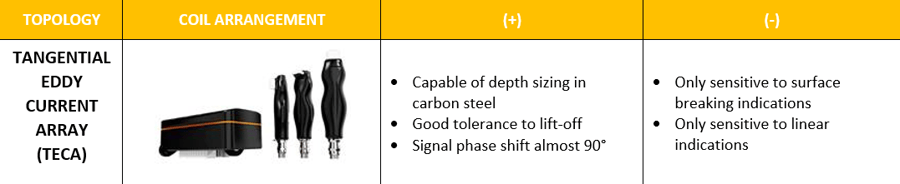
The Tangential Eddy Current Array (TECA™) topology is unique in that it consists of cylindrical shaped coils positioned with their central axes parallel to the surface. This positioning allows the eddy currents to flow parallel to the surface, enabling them to dive under cracks, causing a change in the eddy current density at the material surface. This behavior of the eddy currents allows for depth sizing. This topology is limited to carbon steel materials. There is also a set of coils dedicated to locating the beginning and the end of cracks to allow for length sizing.
Eddyfi Technologies has developed and optimized a range of coil configurations for advanced Eddy Current Testing (ECT) applications to suit specific inspection requirements. Contact our team of experts to learn more and stay Beyond Current.