UltraVision is the powerful UT inspection software by Eddyfi Technologies that supports end-to-end inspection technique design, setup, acquisition, and analysis. From the user-friendly UltraVision Touch interface for portable applications to the full featured UltraVision Classic package for the most demanding of inspection tasks, this all-encompassing software delivers precisely what is required to keep operators Beyond Current.
- UltraVision Touch is embedded on the TOPAZ® instruments and this update is available free of charge.
- UltraVision Classic drives the remote data acquisition units such as the Emerald® instrument and can also be used to drive and analyze data from the portable units for increased capability and flexibility.
Software Enhancements for Total Focusing Method
UltraVision (UV) software users benefit from faster TFM setup and acquisition on the already industry-leading TOPAZ64 and Emerald platforms. Moreover, this software extends the use of advanced imaging modes available within UltraVision, including plane wave imaging. It is also possible to save raw data for challenging materials like austenitic stainless steel through the use of dual matrix array probes.
Automatic Frame Size Calculation

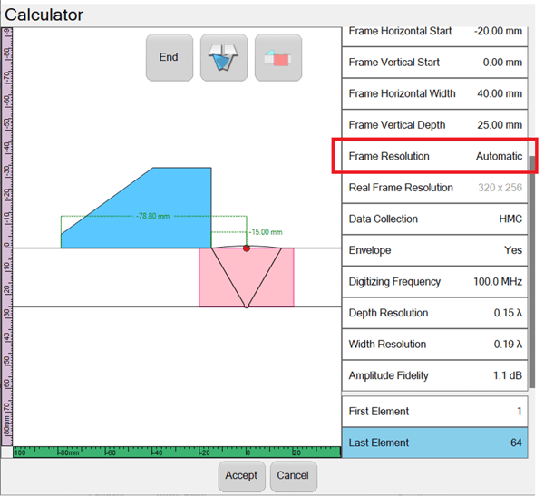
Figure 1: Automatic frame size calculation in UV Touch
When setting up a TFM channel, it is important that the operator set the number and distribution of pixels that will make up the TFM image. The selection of pixel resolution is a balance between optimizing the quality of the calculated image against the resulting file size and scan speed. In addition, it is crucial to emphasize the significance of maintaining ‘Amplitude Fidelity’ in TFM setups. This parameter measures the accuracy of image amplitudes in relation to the real-world maximum amplitude of a reflector. It is directly influenced by factors such as pixel spacing and the wavelength of ultrasound employed. By preserving Amplitude Fidelity, we ensure that the recorded image faithfully represents the true amplitudes observed during the inspection process.
The “Automatic Resolution” feature is set by default (Figure 1) to select a suitable resolution that respects an amplitude fidelity of less that 2dB as specified by standards. It is still possible to manually select a desired resolution up to 1 million pixels for live TFM. This allows fast operator setup for code compliant inspection while retaining flexibility where it is needed.
Improved TFM Image Calculation Speed
Thanks to the powerful capabilities of TOPAZ64, UltraVision software offers a highly responsive user interface that streamlines the setup process, reducing the time required to get started. In particular, when performing total focusing method, the calculation of the TFM frame is now faster than ever before.
When all the necessary parameters have been set in UltraVision, the TFM calculation is carried out in a single step, completing within a matter of seconds. This significant improvement in processing speed ensures that you can swiftly move forward with your inspections, saving valuable time and maximizing efficiency.
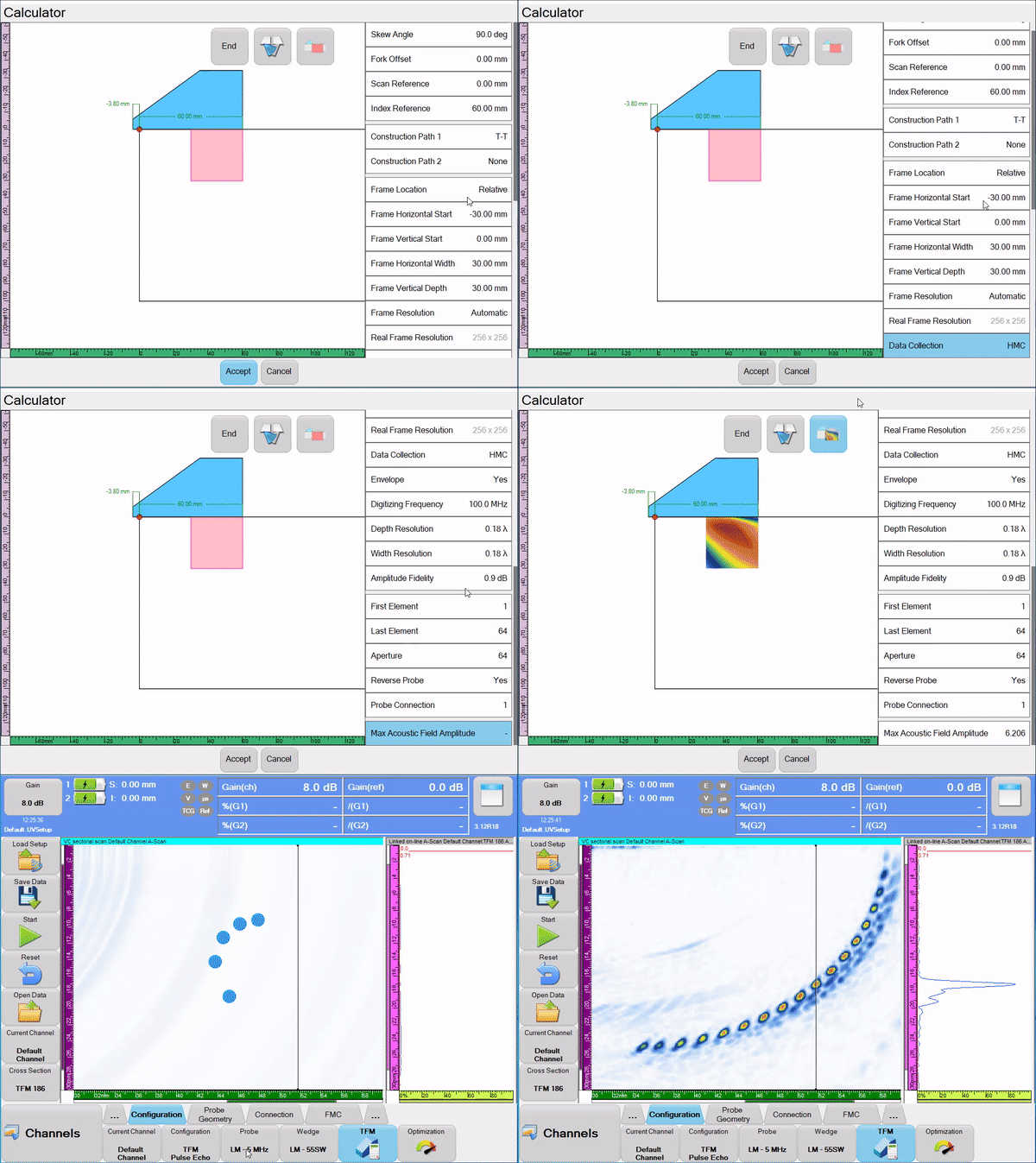
Figure 2 shows an example of the TFM image calculation with the calculator selecting automatic resolution and showing the TFM acoustic field.

FIGURE 2: TFM image calculation
Increased Performance For Saving Raw FMC & PWI Data
In many applications, real-time total focusing method modes are performed directly on the instrument using either FMC or PWI firing modes. The advanced capabilities of TOPAZ64 and Emerald instruments enable the option to capture raw FMC or PWI data for offline post-processing, offering enhanced flexibility in data analysis.
With UltraVision, you can capture raw FMC or PWI data in two distinct modes. First, in snapshot mode, raw data can be captured from a single probe position to provide a detailed representation of a specific point in the inspection. This mode is particularly useful when focusing on specific areas of interest.
Secondly, for encoded scans, UV allows the capture of raw data for the entire inspection. This means you can reconstruct raw data for a single frame or complete duration of the inspection to provide a comprehensive dataset for in-depth analysis and further processing.
Operators can create offline TFM images from captured raw data, enabling exploration of various parameters including wave paths, resolution, and reconstruction algorithms. This flexibility allows you to optimize the results for even the most demanding applications available advanced algorithms in UltraVision Classic include:
- DAS – Delay And Sum
- DMAS – Delay Multiply And Sum
- PCF – Phase Coherence Factor
Overall, UltraVision software continues to increase performance, clearly evident with raw data scanning and recording speeds.
DMA Configurations Available For PWI/TFM
The use of PWI with dual matrix array probes in pitch-catch mode brings great benefit to the inspection of challenging, course grained materials such as austenitic, corrosion-resistant alloy (CRA), dissimilar metal, and cast stainless steel.
With the multiple-element aperture firing in PWI mode, we can find improved Signal-to-Noise Ratio (SNR) in challenging materials while achieving much faster scanning speeds compared to FMC firing, all while taking advantage of the TFM imaging approach.
For more information on the use of FMC and PWI with DMA probes, check out this Coffee Break with Eddyfi Technologies.
Software Enhancements For Phased Array
S-Scan View Smoothing For PA Channels
UltraVision software offers a smoothing option specifically designed to enhance the quality of phased array sectorial views without compromising fidelity. Traditionally, improving the sectorial view image involved increasing the number of focal laws, or beams, used in the inspection. However, this approach had implications on data file size and scan speed due to the increased number of recorded A-scans. With this smoothing filter implemented in the S-scan view for PAUT channels, we achieve a significant improvement in image appearance while reducing the number of required focal laws. This breakthrough feature allows increased scan speed and decreased data file size, all while preserving the necessary resolution for accurate inspections.
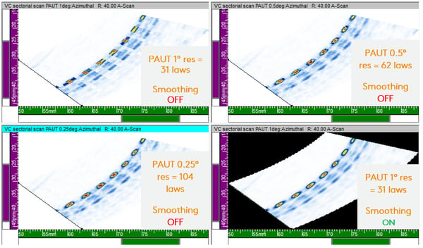
Figure 3 compares the smoothing feature enabled for PAUT sectorial views when displaying a set of radiused 2-millimeter (0.08-inch) Side-Drilled Holes (SDH) on the type B phased array test block. Each was carried out simultaneously with a standard 5MHz 64-element, 0.6mm (0.02in) pitch phased array probe with a nominal 55-degree shear wave wedge, creating beams from 40- to 70-degrees inclusive. It is clear that when not using smoothing, the holes are detected with 1-degree resolution but the images drastically improve for 0.5 degrees and 0.25 degrees sequentially. However, the number of focal laws do too. The bottom-right display shows the 1-degree resolution data, this time with the smoothing option enabled. You can see the imaging of the holes is greatly improved without the need for additional focal laws.

Figure 3: Comparison of PAUT s-scan smoothing on SDH
This new smoothing feature can be enabled in the view properties for the sectorial display. When hidden defects thought they were being smooth, we bet this isn’t what they meant. Take a closer look in this quick video.
Visit our eStore to build your custom quote and contact us and contact us to talk more about your next defect stalk.


