
Back in 1988, inspecting storage tank floors was a laborious and error-prone process, involving manually sampling spot ultrasonic thickness measurements in a sparse grid-like pattern. A common approach was to record five-point measurements per plate, which resulted in less than one percent inspection coverage! But then came Saunderson's revolutionary solution: Magnetic Flux Leakage (MFL)1. Since then, MFL has come a long way and is now a widely recognized and established inspection method known for its ability to provide rapid, efficient, and comprehensive coverage of large ferrous structures such as the floors of Aboveground Storage Tanks (ASTs).
Tank floor inspections are critical to ensuring the safety and integrity of storage tanks, especially in the critical zone, defined by API Standard 653 as the portion of the tank bottom or annular plate within 76.2 millimeters (3 inches) of the inside edge of the shell, measured radially inward. In the past, inspecting the critical zone involved time consuming, fallible processes relying heavily on inspectors' integrity and Non-Destructive Testing (NDT) equipment limitations. Reporting on features detected in dead zones was a wholly manual process, and the actual coverage in these areas was impossible to record. Often, a secondary MFL tool was deployed in this area, without mapping capabilities. Over the previous decades, the industry has lived with a significant mismatch between actual inspection coverage and reported inspection coverage. However, with advancements in magnetic flux leakage scanners, and Eddyfi Technologies' Floormap®X, the process has become more reliable, efficient, and intuitive.
Typically, MFL scanners have been designed to scan in straight lines only. In fact, we invested significant resources in the past to ensure they could do just that! This is not ideal when the structure we are inspecting is circular. FloormapX breaks this coverage barrier with its “Precision Active Steering” feature, enabling fast, high-quality curved scans recorded in the critical zone. This significantly increases coverage in these areas by placing sensors where they are needed most: within 12 millimeters (0.472 inches) of the tank shell.
FloormapX also offers a new “Angled Scan” feature to cover the dead zones at the end of sketch plates, which, as shown in white in the image below, can be significant. Dead zones are reduced, Ultrasonic Testing (UT) scrub requirements are minimized, and there is less reliance on additional ‘mini’ MFL tools. The overall inspection time is reduced through use of a full-sized, automated MFL scanner that reaches more of the tank floor. The actual inspection coverage achieved is recorded within the FloormapX data set and seamlessly displayed within the automated SIMS™ PRO data report.
The ability to scan and record data sets at previously classed dead zones has increased overall inspection coverage, quality, and traceability, providing engineers with actionable data and confidence to determine the integrity of the tank bottom.
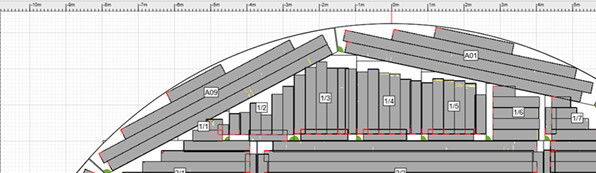
Figure 1: Tank floor coverage achieved with primary MFL equipment without curved scan and add custom scan capability
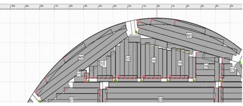
Figure 2: Mapped tank floor coverage possible with FloormapX, including curved and angled scan capabilities
In Figure 1 there are sizeable dead zones shown around the perimeter of the tank and along the angled edges of the sketch plates. These areas may, or more importantly, may not have been covered with alternative inspection methods. In Figure 2 the FloormapX “Precision Active Steering” and “Angled Scan” features were used to achieve comprehensive coverage around the tank perimeter and along the angled edges of sketch plates. As you can see, dead zones are minimized - pretty impressive!
With the cutting-edge equipment and advanced MFL technology offered by Eddyfi Technologies, tank inspections are now done with finesse and precision, rendering extensive UT scrubbing a thing of the past. The result is a seamless, high-quality inspection that guarantees reliable results.
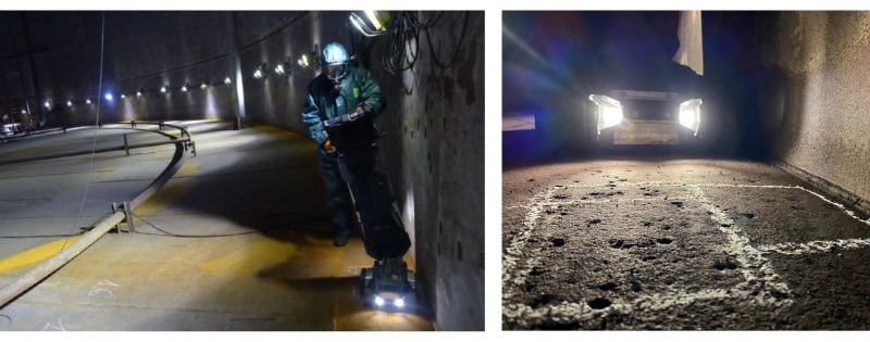
Figure 3: FloormapX scanning the outer curved critical zone where the tank shell meets the floor plates
Eddyfi Technologies recognizes that acquisition speed must be optimal, and NDT equipment and software should be intuitive to ensure a seamless and reliable inspection. The transition stages from mobilization to report submission should be efficient, repeatable, and intuitive, utilizing the latest technological advancements in MFL.
Interested in learning more about MFL? Check out this free course at the Eddyfi Academy!
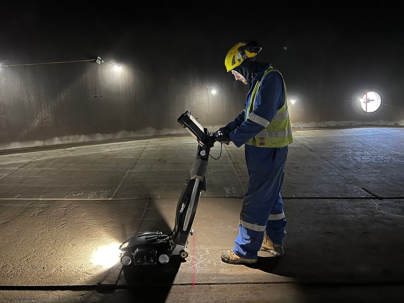
Figure 4: Performing EEMUA 159 tank inspection with MFL tank floor scanner FloormapX (photo credit: C&D Access)
From Saunderson's initial proposal to today's advancements in MFL technology, the inspection of aboveground storage tank bottoms have come a long way, ensuring that recipients of highly accurate and reliable reports can make key repair decisions or remaining life calculations with confidence. Check out this application note on paperless tank inspection reporting to learn more.
Overall, tank floor inspections are a multi faceted process that requires many factors to develop the most effective maintenance and repair plan. Critical to ensuring the safety and integrity of ASTs, the quality of the inspection report is only as good as the equipment used. With continued technological advancements in magnetic flux leakage, particularly the ability to include previously unscanned areas like the critical zone, storage tank floor integrity assessments have become more reliable, efficient, and intuitive. These advancements have improved inspection accuracy and coverage, ultimately leading to safer operations and greater peace of mind for asset owners. As technology continues to advance, we can expect even more accurate and reliable tank inspection reports, ensuring that asset owners can make informed decisions with confidence.
Subscribe to our blog to stay Beyond Current and receive NDT news direct to your inbox including an upcoming article that takes a closer look at the inspection efficiency and data integrity offered by the FloormapX with SIMS PRO software.
Get instant pricing for the FloormapX MFL array tank floor scanner at our eStore and get in touch with our friendly experts who are on standby to answer your specific questions today!
References
1 D. H. Saunderson. The MFE tank floor scanner - a case history. IEE colloquium on non-destructive evaluation, 1988.