
Many NDT methods have been considered for the detection of corrosion on the sealing face, but it was really the development of phased array that allowed operators to manage this risk non-intrusively. Traditional management included the ‘splitting’ of flange joints during outages and inspectors would perform visual inspection to determine the condition. This mechanical splitting process is clearly very costly and can only be performed when the system is offline. The implementation of phased array was accepted by the oil and gas industry as a clear improvement to safety and performance.
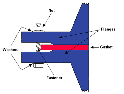
Figure 1: Cross-section of a raised face joint
The introduction of industrial phased array was initially directed towards weld inspection and replacing radiography for construction projects. Soon after it was recognized as a perfect solution for inspecting complex geometry components with its ability to electronically focus ultrasonic beams on areas of concern.
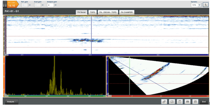 Figure 2: Example of encoded phased array data showing corrosion on the sealing face
An industry sponsored project was launched in 2011 with many oil and gas providers agreeing that phased array was suitable for replacing visual inspection and today, asset owners will use phased array to confirm the fitness of service of flanges and also help plan the maintenance work in shutdowns.
A phased array system is capable of generating numerous angles of inspection and setup designs can be made to meet the exact configuration of the component. Using small footprint phased array probes, operators can scan from numerous locations on the joint. Although the outer rim and bolt face are commonly used, it is from the taper neck where 100 percent of the sealing face is achieved. Combining numerous scan positions can help maximize detectability of corrosion.
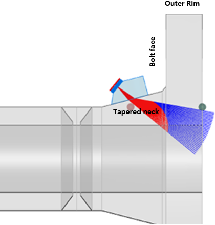 Figure 3: Beam simulation software to help select angles for full coverage of sealing area
In addition to the general principles of phased array being perfectly suited to test a flange, Eddyfi Technologies has also introduced specific software features and scanning systems to improve the reliability of data collection and interpretation.
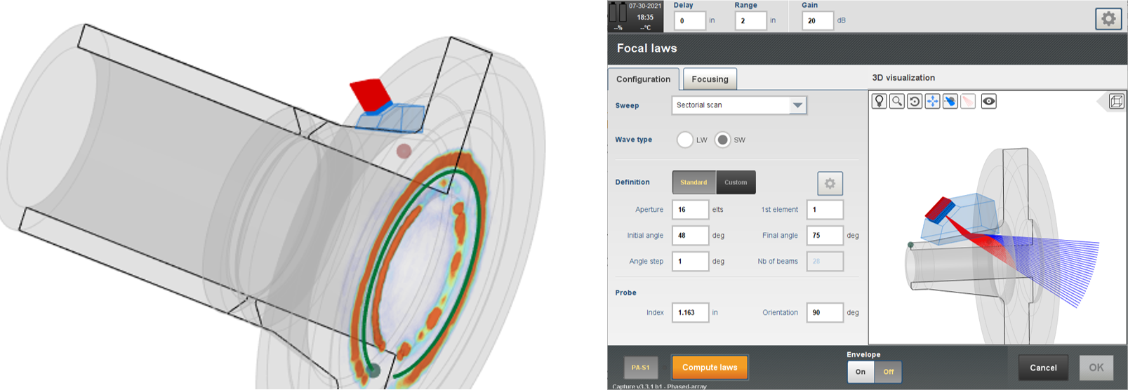
Figure 4: 3D CAD overlay used to improve technique design and interpretation of results
One of the key benefits of advanced phased array systems is the ability to record data sets and analyze the data as complete scan files. This recorded data not only improves quality assurance and traceability but also helps with pattern recognition when considering geometric responses from complex configuration. If operators are able to display full data sets following an encoded scan, then they can use the analysis tools to focus on susceptible areas of the sealing face and easily identify changes that occurred due to corrosion.
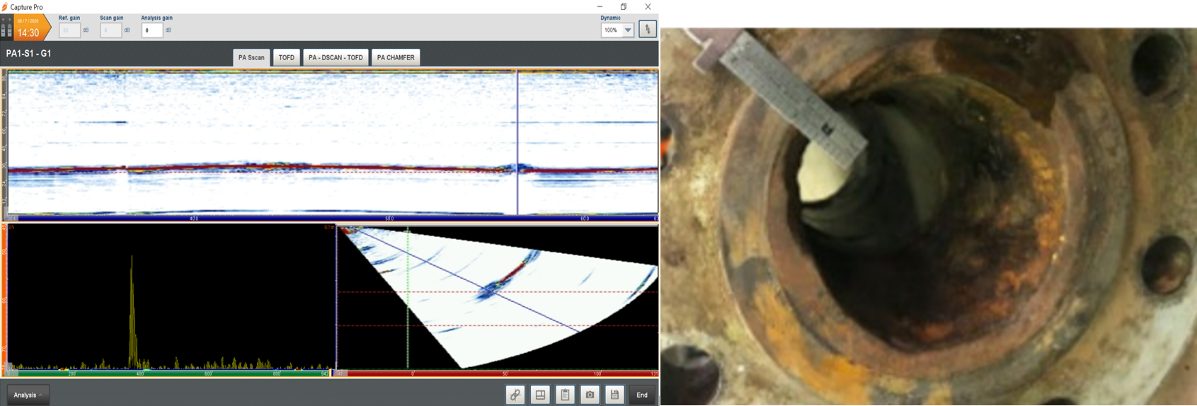
Figure 5: Analysis of flange face corner and the change in response on the encoded scan (left) and typical corner corrosion being physically measured (right)
To be able to perform an encoded scan, it is necessary to have a suitable scanner. The versatile LYNCS™ scanner from Eddyfi Technologies can be adjusted to scan from the tapered neck of a flange and therefore provide full circumferential coverage of the sealing face. The LYNCS design is modular, and the magnetic tractors can be repositioned to help inspect with limited coverage. Having the contactless encoder built into the tractor helps with perfect data acquisition and alignment. It is appreciated that some inspections are restricted for the use of a scanner and particularly flanges that are connected to pipe bends, however with the use of a mini wheel encoder or even scanning manually, phased array can still provide adequate coverage and help eliminate unnecessary plant shut down.
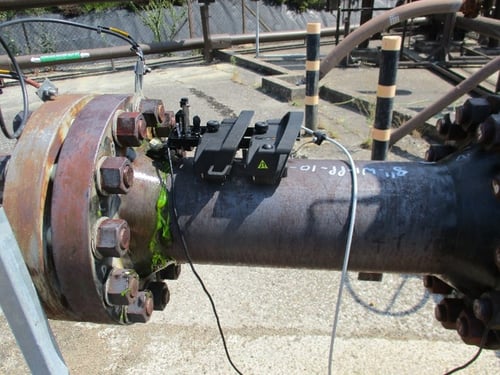
Figure 6: Modular LYNCS scanner that has been assembled to inspect a pipe spool
In conclusion, recently advanced software tools have greatly improved the user interface for phased array inspection of flange faces. The unique ability to map 3D data sets on predetermined CAD overlays increases the visualization of the information and also can improve probability of detection. Although not always practical, having a mechanical scanner that can encode phased array information and improve offline analysis is a significant advantage for detectability and also can provide asset owners with the assurance of inspection quality. Hear firsthand from guest blogger, Jonathon Edgington, who explains how the Gekko® portable phased array instrument with embedded Capture™ software and LYNCS scanner enable more informed decisions with the ability to visualize inspection data on in-service flanges here. I also invite you to contact our team of friendly experts ready to discuss your next inspection challenge today and stay Beyond Current!