
Investigations from pipeline failures within casings at crossings have indicated that casings can lead to potentially unsafe conditions. These conditions include atmospheric and galvanic corrosion and longitudinal pipeline stresses due to carrier pipe flexure inside the casing. The costs of gaining access to these pipe regions for inspection via conventional NDT methods can make it prohibitively expensive.
This problem becomes even more significant when considering road crossings in oilfields. Excavating road or pad crossings can cause severe access issues to other areas of the oilfield. In some cases, significant time and expense go into constructing temporary roads or diversions to allow the free flow of oilfield traffic while the crossing is excavated and casing removed to allow access for traditional NDT inspection methods.
Eddyfi Technologies guided wave inspections offer significant advantages over other NDT methods as it does not require direct access to the cased section of pipe. The transducer collars can be placed on either side of the cased section allowing the cased area to be examined from two separate locations. Inspecting from both sides of the crossing increases the results' confidence and maximizes the chances of obtaining 100% coverage. In addition, no access is required inside the cased section, so there is no need for expensive excavation or casing removal. Road crossing inspections can take many forms. Examples include buried cross-country pipelines, above-ground desert pipelines, and insulated pipelines on North slope oilfields.
Our inspection solution has been employed globally with great success. For example, Pertamina Algeria required an accurate assessment of many of its pipelines in the Sahara Desert, North Africa. As part of these campaigns, many road crossings needed inspection. These road crossings were of particular concern as they did not benefit from cathodic protection. The crossings, in this case, were not cased but directly buried in the sand. The location in Figure 1 was of considerable importance as it was the main supply road in and out of the oilfield. Access was available from either side of the crossing.
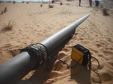
Figure 1: Desert Road Crossing
Once data was collected, the A-scans from each side of the crossing were compared to establish any suspicious indications. During analysis of data obtained from test location 1 (south side of the crossing), girth weld 858 was highlighted as displaying an unusual echo dynamic response. Instead of displaying a uniform symmetrical trace, weld 858 displayed a double peak signal and a higher-than-expected flexural response, as shown in Figure 2.
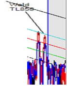
Figure 2: Girth Weld 858
The suspect region was further scrutinized from test location 2 (north side of the crossing). On review of this region from test location 2, it was clear that the girth weld had two anomalous signals adjacent to it, as shown in both the A-scan and A-Map displays in Figure 3.
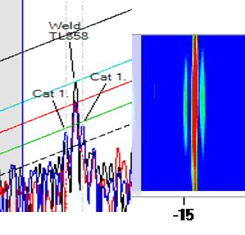
Figure 3: A-scan and A-Map displays of weld 858
Based on the evidence collected from both test locations, the inspection team recommended localized excavation to investigate the suspect signals. Due to the pipe's nature and location, follow-up work was undertaken immediately which identified a significant externally corroded area. This large section of pitting corrosion had an axial length of around 1 meter (3.3 feet) and extended approximately 180 degrees of the pipe circumference. The wall thickness measurements showed up to 75% loss in the deeper pits. An image of this region is shown in Figure 4. Girth weld 858 is just visible in the bottom left portion of the picture.
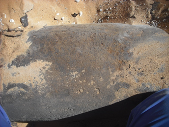
Figure 4: External corrosion identified beneath the road crossing
Another excellent example of a road crossing application is those conducted in Alaska's north slope oilfields. These pipelines are predominantly above grade, polyurethane foam insulated pipelines that pass through the casings at road and pad crossings. Guided wave inspections of this type are commonplace in this region and have been undertaken since 1998. The crossings can be up to 75 meters (246 feet) in length, and the pipe diameters typically range from 75 to 762 millimeters (3 to 30 inches). The pipe contents are usually either oil, gas, water, or a combination. One of the main problems experienced in this region is weld pack corrosion. Weld pack corrosion is caused by meltwater ingress at field applied weld packs. As a result, the end users must excavate a number of lines as part of their annual inspection schedule. Excavation is based on several factors such as regulations, risk ranking, replacement programs, and guided wave inspection data.
During these inspections, the end user provides (where possible) access to both sides of the road or pad crossings. This increases the chance of obtaining full coverage on longer sections and also provides an opportunity to increase confidence by having crossing data obtained from two separate locations. Figure 5 highlights a typical road crossing. The insulation is removed at each end of the casing to allow access for Eddyfi Technologies collars. The A-scan data in Figure 5 displays the data collected from both sides of the crossing (TL01 – Northside & TL02 Southside). To ensure that these two data sets can be easily compared, they need to share the same datum point. In this case, the Northside casing entrance was selected as the datum (highlighted by the red arrow).
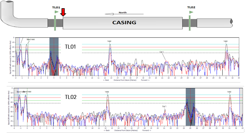
Figure 5: Typical crossing configuration and A-scan data
When the same datum position is used, the axial distances will correspond between the two data sets. The inspection from TL01 identified a low amplitude signal at ~ 21 meters (69 feet) from the datum. This signal was also identified from TL02. Having both sets of data displaying the signal at the same axial location increases confidence in making the call. We offer some best practices for inspecting this type of cased crossing.
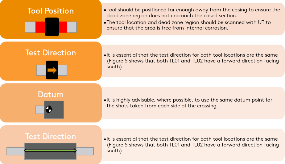
Figure 6: Best practice tips for inspecting above grade cased crossings
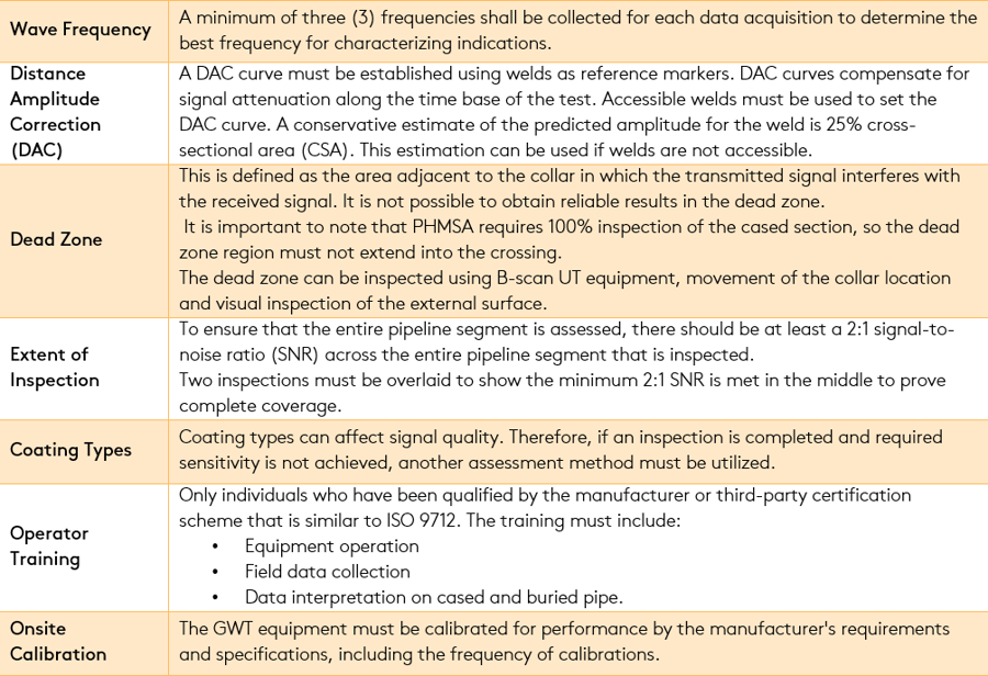
These tips are not exhaustive; however, they will undoubtedly help simplify the inspection process. Additional information on the inspection of cased crossings can be seen in the Pipeline and Hazardous Materials Safety Administration (PHMSA) 49 CFR Appendix F to Part 192 - Criteria for Conducting Integrity Assessments Using Guided Wave Ultrasonic Testing (GWUT). This document is designed to facilitate the successful implementation of guided wave UT for cased crossings. This document ensures that guided wave operators no longer need to notify PHMSA to use guided wave testing for this application. This is also a good guide for carrying out the inspection of crossings generally. The main points of the document are highlighted below.
Further information regarding PHMSA protocol has been published in this article.
Guided waves have been shown to have enormous benefits for the inspection of road crossings due to the novel capability of the technology. It can inspect regions of pipe without needing the tool to be directly above the area of interest. This means that road crossings can be inspected by accessing the pipe on either side of the casing without disruption. Over the years, this technique has become more established. It has now reached a point of maturity where regulators are defining best practices for this method to be used more widely.
Eddyfi Technologies offers the leading-edge guided wave ultrasonic testing equipment and training to ensure the best possible results. Contact our team of experts to discuss your next inspection job and stay Beyond Current.