
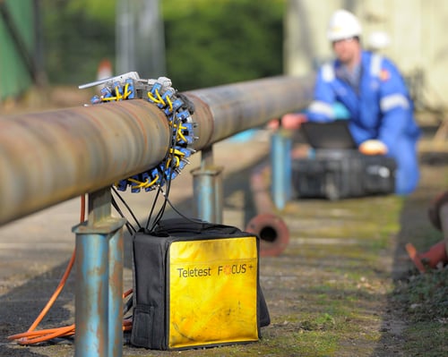
Guided wave testing uses a low-frequency ultrasound operating between 20-100kHz compared to the conventional ultrasonics MHz frequency range used for thickness checks. This allows the ultrasound to be broadcast away from the tool and axially along the pipe in GWT. When this broadcast ultrasound encounters a change in cross-section, the change in acoustic impedance of this region causes an echo of sound to return to the tool for detection. Using the welds on a pipe for calibration and comparing amplitudes of other signals to these welds, it is possible to indicate the severity of any corrosion detected. Furthermore, using additional advanced methods such as C-scan imaging techniques and, in Eddyfi Technologies’ case, a unique secondary focusing method, it is possible to give angular positioning and circumferential extent. However, even with all this post-processing currently, minimum remaining wall loss is not possible using GWT.
Long range ultrasonic testing has two major selling points that differentiates itself from other techniques. These selling points are the primary reason why the method is considered a valuable tool in a pipeline inspection program. The first attribute is productivity, and second is its almost unique ability to inspect pipe areas without the probes being situated directly over the area of interest. Let’s take these points in turn.
Productivity
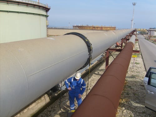
The most common piping applications using GWT are aboveground piping, long straight lengths with thin/no coatings. For this situation, it is expected that the technique should easily achieve tens of meters in both scan directions (over 100 meters have been achieved in the field). For this example, I will consider a 300-millimeter (12-inch) pipe with a readily achievable diagnostic length of 25 meters (80 feet) in each direction. The 300-millimeter (12-inch) line has a circumference of approximately 1 meter (3 feet). With the 25-meter (80-feet) range, this equates to a 50m2 (540ft2) of surface area inspection coverage per location. Also, suppose you consider that this inspection is expected to take less than an hour. In that case, this results in an inspection rate of approximately 1m2 (10ft2) per minute. In addition, this is scalable, so a 600-millimeter (24-inch) pipe has double the circumference and therefore an inspection rate of 2m2 (20ft2) per minute. These inspection rates are considerably greater than most scanning methods with 100% volumetric coverage achieved.
Inaccessible or Difficult-to-Access Piping
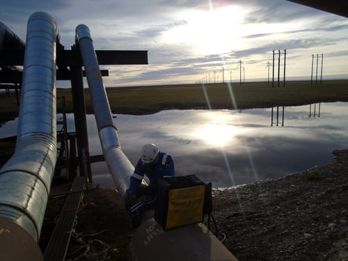
Whether it is a simple elevated line in a refinery, a jetty line, or even a critical road crossing, these inaccessible or difficult-to-access areas of pipelines can cause a significant headache for end users. Inspecting these areas with localized techniques may require access platforms, expensive scaffolding to be erected, or even excavating the pipe itself. Due to the unique ability of GWT inspecting areas away from the tool location, it is possible to cover these pipeline regions from a more easily accessible point which translates into significant cost savings.
Visual Data Paints a Thousand Words
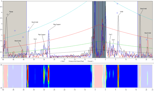
The final point that is often overlooked for a pipeline inspection program is that the LRUT data and reports are quite a visual document with DAC scans, tables of pipe features, and C-scan images that contain all the required information for easy follow-up and reference. The inspection reports usually correlate closely with a scope of work, making it very easy to prove complete inspection with all the data being fully recordable, traceable, and auditable when required. End users have found this particularly useful in the past.
So, how do guided waves fit into a pipeline inspection program?
Guided wave ultrasonic testing is a crucial, highly productive screening tool for end users when long lengths of pipeline require assessment to help assist with prioritizing the areas that need more localized sizing based inspection. It also reduces the cost of access for the inspection of pipelines where the situation may only have periodic, easily accessible locations. Even worse, the pipeline may be totally inaccessible. Finally, all of the data is fully recordable, traceable, and auditable, making it easy to correlate to a scope of work proving coverage and condition when required.
When it comes to guided wave instruments that can truly go the distance, look no further than Eddyfi Technologies’ proven technology to deliver inspection results you can feel confident in. Check out these case studies clearly demonstrating the versatility GWT offers:
- Testing at Extremes – Small Diameter Pipelines
- Testing at Extremes – Large Diameter Pipelines
- A Cool Solution for Cold Temperature Pipeline Inspection
- Guiding the Way with High Temperature Pipeline Guided Wave Testing
Contact our team of knowledgeable experts to learn more about implementing guided wave testing in your pipeline safety program today!