
Conventional UT is the main ultrasonic technique for the inspection of fusion-welded joints. It has been used for quite some time and international standards such as ISO17640 or ASME V explain the requirements necessary to define the proper procedures for weld examinations, including:
-
personnel qualification,
-
procedure demonstration/qualification,
-
extent of the volume to be scanned,
-
acceptance standards.
Two important parameters to choose are the angle of incidence and the element size when performing weld examination with UT. According to standards, one of the probe angles used shall ensure that the weld fusion faces are examined at, or as near as possible to, normal incidence. The element size shall be chosen according to the ultrasonic path and the frequency used. The smaller the element means the shorter the near field limit and the larger the beam spread in the far field, which in turn means a lower capacity to size small indications.
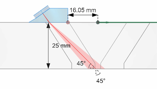
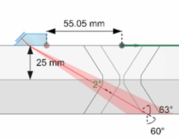
The new scan plan feature in Capture 3.2 provides the angle between the angle of incidence and the bevel and beam spread to allow operators to carefully choose their probe. The following image shows a 9.5 millimeter (0.375 inch) 5-MHz conventional UT probe used to inspect a 25 millimeter (1 inch) 65° V-weld. We use two wedges: a shear 45° and a shear 60°. One can see several annotations in the 3D view:
-
the component thickness,
-
the index offset,
-
the angle between the incident angle and the bevel (same side) on the second leg,
-
the angle between the incident angle and the bevel (opposite side) on the second leg, and the incident angle,
-
and the beam spread.
The scan plan shows that it is barely possible to inspect the weld root using the wedge at 45°. The image on the right shows the scan plan for the SW60 wedge; we can see where the ultrasounds hit the bevel and have an idea of the focal spot size when they hit it. The angle with the bevel is 2°.
 |
 |
Standards also provide guidance on the volume to be tested. The testing volume is defined as the zone which includes weld and parent material for at least 10 millimeters (0.4 inches) on each side of the weld, or the width of the Heat-Affected Zone (HAZ), whichever is greater. One can adjust the index offset manually and see the necessary value to ensure full coverage by looking at the ray tracing and for which positions it hits the bevel.
However, the scan plan introduced in Capture 3.2 is dynamic, i.e., all the annotations adjust in real time based on the position of the probe if encoded. In the following video, we use a string encoder attached to the probe.
The video shows that when the probe is against the weld cap, the ultrasounds are normal to the bevel on the opposite side allowing the detection of lack of sidewall fusion on the first leg. Moving the probe backwards, we see that we need an index offset of about 100 millimeters (4 inches) to ensure examination of the entire bevel same side and the HAZ. The live visualization of the ray tracing helps operators plan the displacement of their probe to ensure the full coverage of the weld.
Most conventional UT inspections are done manually, but it may be interesting to attach an encoder and record data along the index axis for the indication scan positions when indications have been found. By doing so, an operator can obtain the 3D ray tracing presented before associated to the recorded B-scan. The following video shows the acquisition recorded for a lack of sidewall fusion using the previous SW60 configuration. Calibrations were carried out before inspection. Sizing is done using a -6 dB drop and the scan echodynamic. Based on the extremities of the -6dB technique, one can see in the 3D ray tracing image where the ultrasounds hit the bevel and thus the limits of the Lack of Fusion (LOF).
While many applications can benefit from advanced ultrasonic techniques such as phased array ultrasonic testing and total focusing method, one may still want to perform conventional ultrasonic testing inspections. The entry level Mantis™ instrument from Eddyfi Technologies is a cost efficient, lightweight PAUT system that offers conventional UT, TOFD and PAUT techniques. Operators benefit from the advanced scan plan for the three techniques improving productivity and reliability. The Mantis can also be upgraded later to include multigroup and TFM based depending on projects. Contact us to learn exactly how Eddyfi Technologies’ advanced inspection solutions can optimize your next job today!