
Shell approached Eddyfi Technologies for an unmanned solution to inspect the coatings and basic material of the inner tank surface for damage caused by corrosion or erosion, cracks, bumps, pitting, and the like. There was a requirement to inspect the tank wall, bottom, sides, reinforcement rings, welds, and internal structures like drop tubes. Wall thickness testing was required. Finally, the technology needed to be capable of further investigation of any issues identified such as pit depth and area of imperfection.
Just as with a human operator, thorough cleaning prior to inspection is necessary for successful results. During this trial, tank cleaning was not sufficient for complete inspection; however, the robotic inspection system successfully demonstrated its ability to achieve equal and better inspection data collection than manned entry, despite the limiting factor of vessel cleanliness.
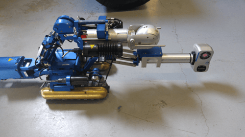
A crawler closely resembling the VersaTrax™ NDT (formerly known as Magg™ R-Scan)was deployed for the remote visual inspection (RVI) and ultrasonic testing (UT) of:
-
The internal elements
-
The welded joints
-
The bottom where settled water could potentially exist
-
The interior surface of the tank wall where only the gas phase of the fuel touches the tank’s interior
-
The internal coatings and basic metal of the inner surface
-
Wall thickness to identify to 1% of original tank thickness (both robotic and manned inspection face the same challenges relating to thickness testing and interior cleanliness is the deciding factor in ability to assess and obtain results).
Remote Visual Inspection
The following images demonstrate the UT-enabled crawler’s ability to effectively inspect the vessel.
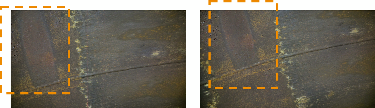
Internal view of welded joints – surface corrosion evident in and around 12 o'clock position – shown in orange box above.
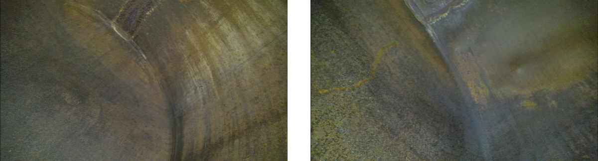
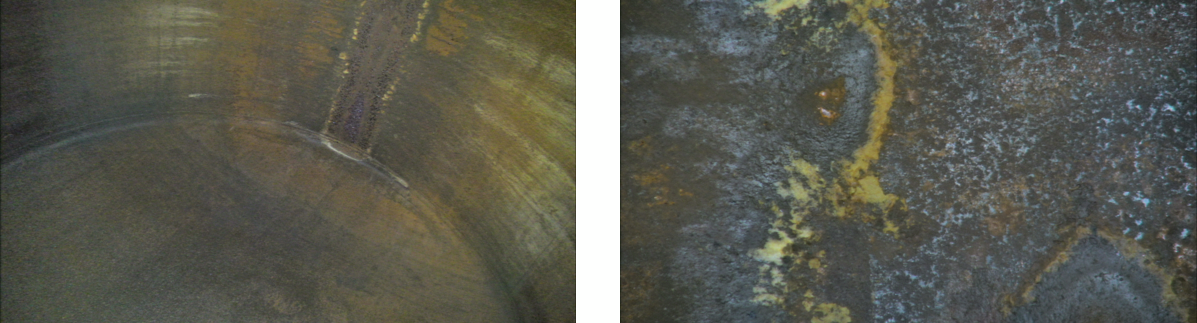
Wide angle view of tank interior surface. Indication of “tide mark” visible, along with mechanisms visible along 1200h position, consistent with maximum fill level.
Additional angle view of tank interior surface. Indication of “tide mark” visible, along with mechanisms visible along 1200h position, consistent with maximum fill level.
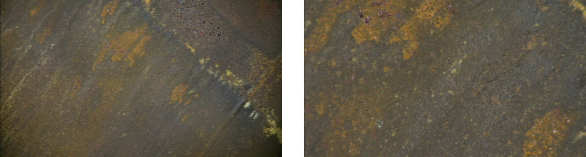
Wide angle and close-up view of 1155h position and evidence of corrosion pitting – additional close-up image shown (right).
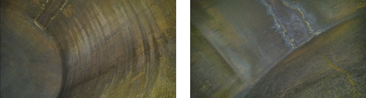
Dome end view (left), with close-up of 1200h pitting in extremity where dome end meets tank wall.
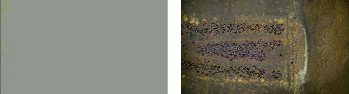
To conclude the RVI portion, we highlight the “DEFOG” function offered with Eddyfi Technologies’ inspection cameras. The following image shows conventional acquisition without defogging on the left versus the defogging mode engaged on the right.
Ultrasonic Testing
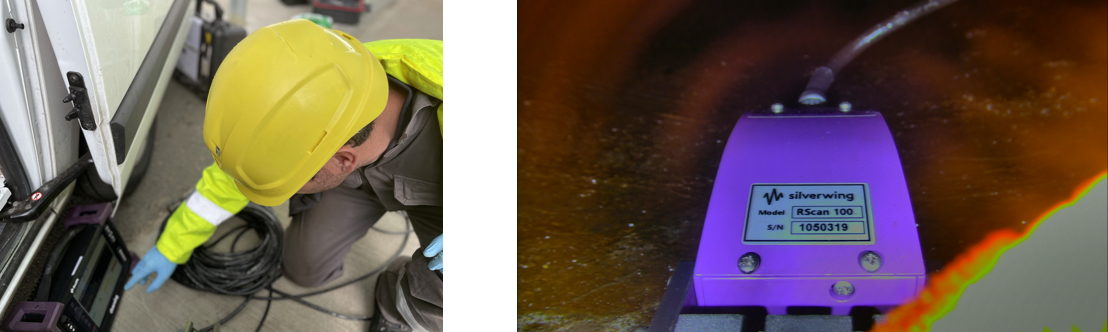
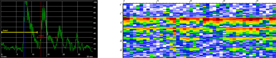
For the UT portion of this trial to identify loss to 1% of original tank thickness, the loosely integrated R-Scan probe together with the touchscreen Swift acquisition device provided the information required while traversing on the VersaTrax M-Series (formerly known as Magg 310) crawler. Prior to this inspection, a calibration block of similar material, i.e., carbon steel, was used with steps at a representative thickness (in this case, 5 and 10 millimeter based on a nominal tank thickness of 6 mm). These were measured to confirm the system’s correct functioning. The following is the output from the Swift instrument, showing accurate measurements for 5 mm and 10 mm, respectively.
Using data from the encoder, we can create a dynamic B-scan of the 5-10 mm calibration block. This can be likened to a cross sectional through cut of a sample.
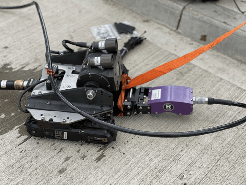
Probe mounted to VersaTrax M-series robotic crawler system
Initial setup and operation of the R-Scan probe was performed using the touch screen Swift acquisition device. Designed for in the field, the touch screen can be used wearing gloves or operated with a pointer. The following image shows the view from the onboard camera showing the R-Scan in clear view.
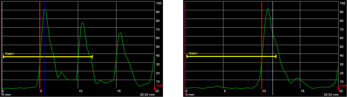
Despite the tank cleanliness not being up to standard for the dry coupled ultrasonic testing used during the trial, some data was obtained. The following A and B scan data shows a back wall echo (including any residue) of 7.4 mm (using the velocity of steel; we were not given a confirmed material). The echo-to-echo measurement, which we would consider as the remaining wall thickness, was measured at 5.4 mm in the area able to be measured.
Photogrammetry
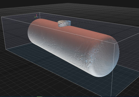
3D photogrammetry is the next step. This is the process of obtaining visual data (images and videos), finding patterns, and making a 3D model based on the same. In a carbon steel vessel, a magnetic crawler allows for the best coverage.
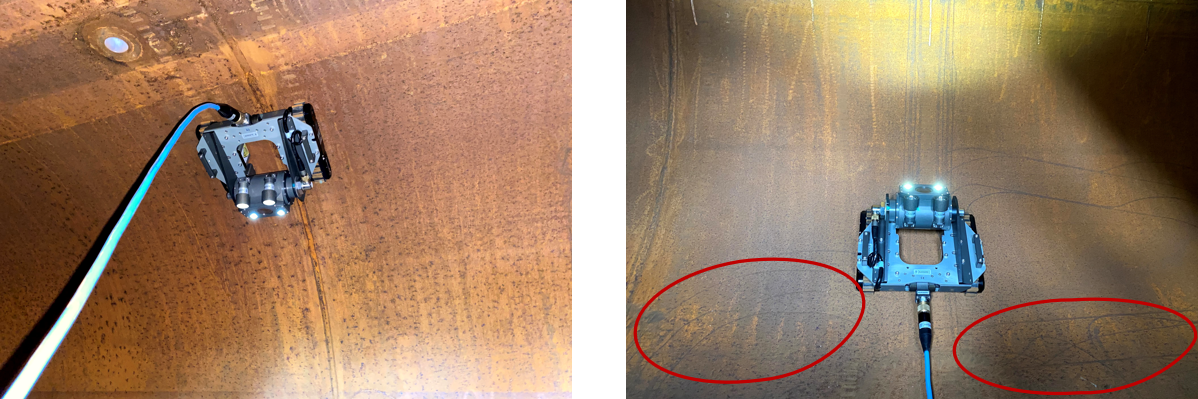
The following image shows the VersaTrax operating inverted inside a vessel with its rubber tracks leaving only marks in the dust during the pass. It’s worth noting the marks/damage left on the vessel wall from a previous non-Eddyfi Technologies wheeled system (right image).
Contact our robotics experts to learn best practices for going from flat images to a fully manipulable 3D model, useful for export, and compatible with most 3D software.
The topographically rendering of the vessel can have UT/laser scanner data added and serves as an ideal baseline for other purposes.
 3D Laser Scanning
For this trial, we operated using equipment available at the time the tank was also available. To mitigate against these constraints of field only trial, Shell Netherlands shipped a sample tank wall to Eddyfi Technologies in Swansea for further testing which allowed us to use a broader range of technology that was available in the field. The following images show the laser scanner in a mock environment, however, in the field it would be robot mounted like the example shown later.
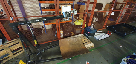
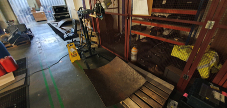
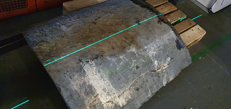
The laser scan line is seen projected on the exterior surface of the tank wall sample below, while the live acquisition data shows the coverage and laser intensity during scanning. The trial data obtained looked at the worst-case scenario. The output from the 3D scanner using Cloud Compare software enables precise mapping, manipulation, and measurement of the plate sample.
 Crawler mounted laser scanner
This trial demonstrated that robotic and remote inspections can inspect the interior surface and overall conditions of the tank to a greater detail than what would have been achieved with manned entry. In this scenario, prior cleaning was not sufficient for complete coverage and a new robotic cleaning solution should be considered. Eddyfi Technologies offers custom robotic solutions for remote applications like cleaning – learn more about OnSpec Robotics here.
The use of complimentary techniques (visual inspection, laser scanning, and ultrasonic testing) is essential for the coverage required to make adequate analysis ahead of decision making. Alternative techniques including pulsed eddy current, eddy current array, tangential eddy current array, phased array ultrasonic testing, alternating current field measurement, and more developed in-house by Eddyfi Technologies can be integrated with our robotic systems used during this trial.
I’ll continue to reiterate this: better information equals better decision making. No other company offers the full suite of advanced solutions that Eddyfi Technologies can leverage to enable a permanent record of inspection and a digital twin – no manned entry required. Contact us to discuss how our synergistic solutions can improve your operations today!