Definition: Why Stainless Steel Welds Are Challenging for PAUT
Stainless steel welds can be anisotropic and coarse-grained, which causes ultrasonic energy to scatter and the beam to steer away from the intended path.
These effects are most problematic with shear waves, so stainless steel procedures commonly use angled compression waves to improve beam stability and SNR, then add dedicated coverage strategies for the near-surface region.
Key idea:
Stainless steel welds can reduce PAUT reliability because grain-related scattering and beam steering can distort beam paths and lower SNR, especially in shear-wave mode.
Although phased array has many advantages over other NDT methods for weld inspection, it still has similar restrictions as conventional ultrasonic testing when dealing for anisotropic materials. Materials such as stainless steel can cause problems for ultrasonic methods, as the grain structure is not homogenous and can also be quite coarse. These features can affect attenuation and cause problems such as scatter and beam steering.

Figure 1: Scattered Sound Beam
Practical decision:
If your current shear-wave setup shows unstable beam paths or poor SNR in stainless steel, switch to angled compression waves as the baseline approach, then redesign coverage (no skip + near-surface coverage).
The beam steering and scatter is most prominent when using a probe in shear wave mode, which is the most common wave mode for testing carbon steel welds. Although lower frequency shear wave can be considered, it is most likely that the phased array technique for stainless steel welds will involve using angled compression waves. Compressional waves have a more favorable wave propagation, and with double the wavelength, is less affected by the coarse grain structure of the welds.

Figure 2: Comparison of Shear Wave (left) and Angled Compression (right)
Angled Compression Waves: What Improves and What Breaks
Angled compression waves improve propagation in stainless steel welds, but they remove the ability to use skip paths for full weld coverage and can create near-surface dead zones that must be addressed in the scan plan.
The story doesn’t just end there unfortunately. Angled compression shows a significant improvement for sound propagation but has one critical limitation. With a shear wave beam, the sound can skip from the internal surface of a pipe and bounce up into the weld for interrogation. This skipping setup is what is typically used to gain 100 percent coverage of the weld.
 Figure 3: Shear Wave Phased Array Setup; Skipping Sound from the Internal Surface Covering the Full Weld Volume
With angled compression waves, we are not able to skip from the surface, as when the beam interacts with a boundary it causes mode conversion and unwanted signals. Therefore, when scanning with angled compression, all inspection must be completed on the first pass and the weld is inspected directly.
Key takeaway:
With angled compression, assume first-leg inspection only. Coverage must come from probe proximity, multi-position scanning, and dedicated near-surface techniques rather than skip paths.

Figure 4: Angled Compression Setup on the First Pass (no skip)
As seen in figure 4, the probe on the first pass inspection must be much closer to the weld and this causes a potential dead zone at the surface.
How to Cover the Near-surface Dead Zone (Two Practical Options)
- Option 1: Scan from both sides when access allows (common on large structures such as tanks) to recover near-surface coverage.
- Option 2: Add a creep wave setup in the scan plan, which is highly sensitive to surface defects and can cover the top dead zone when single-side access is limiting.

Figure 5: Creep Wave Setup
Why Dual Matrix Array (DMA) Probes Help in Stainless Steel Welds
DMA probes are designed to improve SNR and focusing capability in challenging, anisotropic weld materials by separating transmit and receive rows and enabling focusing in multiple orientations.
To achieve all of the above, the industry now offers a unique set of phased array probes that are designed specifically for stainless steel inspection. These probes, typically referred to as Dual Matrix Array (DMA) probes, use two rows of elements on a dedicated wedge with one row of elements sending the sound and the other row receiving. The rows of elements in these probes are not linear and are actually diced in two orientations. This design not only allows for increased Signal-to-Noise Ratio (SNR) through the weld material, but also provides the ability to focus on numerous orientations.
What to document in your procedure:
Record the wave mode (angled compression), probe type (DMA vs linear), wedge identification, and the focusing orientations used so the setup is repeatable across operators and shifts.

Figure 6: Phased Array Element Arrangements for a Dual Matrix Array (left) and Standard Linear Array (right)
Calibration and Reference Blocks: What You Need (and Why)
To verify detectability and true coverage in stainless steel welds, build calibration and reference blocks from the same material and weld process as the field welds.
Include at least:
- Side-drilled holes (SDHs) for sensitivity checks and response consistency
- Surface notches to validate near-surface coverage (especially important when using angled compression)
- Coupons for daily checks so probe integrity and sensitivity can be verified before and during production scanning
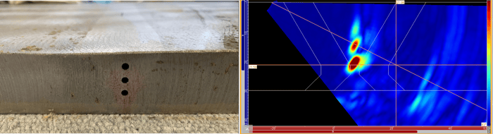
Figure 7: Angled Compression Probe on Stainless Steel Calibration Block Showing Excellent SNR and Detection of the Reference Reflectors
Scanner Selection for Nonmagnetic Stainless Steel Welds
Stainless steel is nonmagnetic, so scanners designed around magnetic wheels for carbon steel may be unstable or unusable. Use a scanner that provides consistent probe pressure, positional stability, and encoder accuracy on nonmagnetic surfaces.
The final consideration for this type of inspection is the mechanical scanner. Unfortunately, most weld scanners are designed to be used on carbon steel material with a magnetic wheel system. As stainless steel is nonmagnetic, an advanced modular ultrasonic inspection scanner built for phased array (PAUT) corrosion mapping and PAUT/Time-of-Flight-Diffraction (TOFD) is required. The system allows operators to switch between weld inspection and advanced corrosion mapping rapidly.
In this instance and for pipe welds, we recommend using the chain scanner; this scanner has all the benefits of the weld inspection configuration and provides stability when scanning nonmagnetic materials.
Key takeaway:
If your scanner cannot maintain stable probe coupling and repeatable positioning, your stainless steel PAUT results will vary more than your technique settings. Treat scanner stability as a primary qualification variable, not an accessory choice.
Beyond stainless steel, the inspection scanning solution is applicable for high-density polyethylene (HDPE) pipework. Paired with world class portable PAUT instruments offering Total Focusing Method (TFM) and Plane Wave Imaging (PWI) like Cypher®, operators can truly optimize their HDPE ultrasonic inspections.
Practical Checklist: Implementing PAUT for Stainless Steel Welds
- Confirm stainless steel weld type and grain condition (cast vs wrought, austenitic, dissimilar metal) because this drives scattering and beam steering risk.
- Start with angled compression waves when shear-wave propagation is unstable, then design the scan plan assuming no skip coverage.
- Explicitly cover the near-surface dead zone using either both-side scanning or a creep wave setup.
- Select probes suited to anisotropic welds (for example DMA probes) when SNR or focusing orientation is limiting.
- Fabricate calibration blocks from the same material and weld process, including SDHs and surface notches, and use coupons for daily checks.
- Choose a scanner compatible with nonmagnetic surfaces and validate encoder stability and probe positioning repeatability before production scanning
In conclusion, phased array is most certainly becoming the method of choice for weld fabrication and has replaced radiography for many inspection projects (just check out this blog on 3 weld inspection challenges solved by advanced UT in lieu of radiography). Although assessment is possible on non-homogenous materials, the operator must carefully select the probes, have experience in calibration requirements, and choose a scanner that provides stability and probe accuracy when the surface in nonmagnetic.
Eddyfi Technologies is committed to delivering the best of all worlds to ensure inspectors can collect the data required for actionable insights. Contact our team of experts to discuss your next inspection campaign and learn how to stay Beyond Current.