
When it comes to the inspection of flanged joints, many Non-Destructive Testing (NDT) methods have been considered for detecting corrosion on the sealing face; however, it was really the development of Phased Array Ultrasonic Testing (PAUT) that allowed operators to manage this risk non-intrusively. Traditional management included the ‘splitting’ of flange joints during outages, and inspectors would perform visual inspection to determine the condition. This mechanical splitting process is clearly very costly and can only be performed when the system is offline. And that’s why the implementation of PAUT was accepted by the industry as a clear improvement in terms of both safety and performance.
The raised face flange is the most commonly used type. Like the name suggests, it has a raised area machined on the flange face equal to the contact area of a gasket. This is the most critical area for the prevention of leaks. Crevice corrosion may occur in the crevices or gaps between the flange and the mating surface of the pipe or where it connects with equipment. This type of corrosion is often caused by the accumulation of aggressive chemicals or the depletion of oxygen within the crevice. Corrosion in the sealing area can lead to loss of containment, posing a significant risk of releasing the product and causing a catastrophic effect.
The areas of inspection can be segregated into three main regions: the flange bore (1), the flange corner edge (2), and the raised sealing face (3).
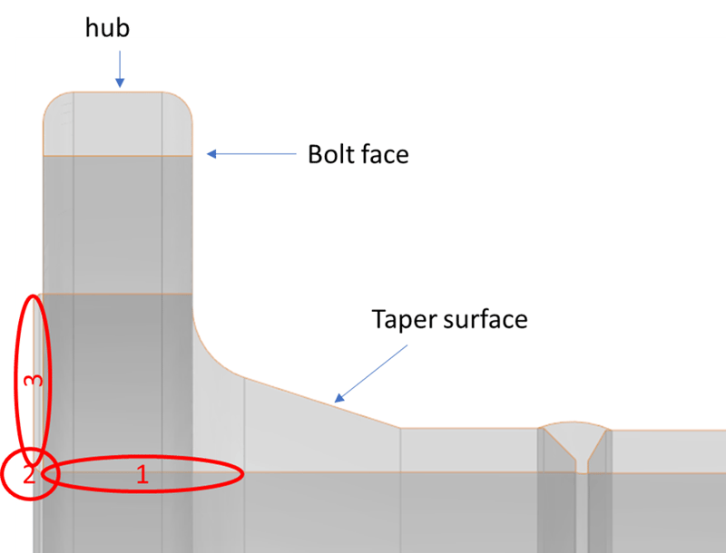
Flange bore: This area of the flange is the internal diameter indicated by area 1 in the previous image. The corrosion mechanisms for the flange bore are largely the same as those for the pipe where the flange is connected. Corrosion detected on the flange bore should be viewed in the same light as internal corrosion of the surrounding pipe with the key variable being minimum thickness.
Flange corner edge: The corner edge of a flange, indicated by area 2 in the image, is the transition from the bore of the pipe to the sealing surface of the flange itself. Typically in a raised face flange, the gasket acts as a seal and covers the area of the raised face all the way from the corner edge to the end of the machined surface of the raised face. Although corrosion of the corner edge does not immediately threaten the flange seal's integrity, the loss of this edge can create a crevice that traps aggressive chemicals, initiating and propagating the corrosion process, which can eventually extend into the gasket area.
Raised sealing face: The sealing face of a flange refers to the machined surface that spans from the corner edge to the outer radius of the flange. This area is typically covered by the sealing gasket, and any corrosion on this raised face can significantly impact the flange's sealing effectiveness, leading to leaks or system failures. Moreover, the corrosion can cause damage to the gasket, necessitating replacement and potential downtime for the system. Therefore, it's critical to regularly inspect and maintain the flange's sealing face to prevent corrosion and ensure the safe and efficient operation of the piping system.
How to Leverage 2D CAD Imports for Flange Corrosion Detection
It is necessary to establish a scan plan to ensure full coverage of these three areas. While it is possible to draw the flange and the rays on a piece of paper with a pencil to establish the positions and angles necessary to ensure full coverage, who wants to do that? This method is obviously not the most convenient and doesn’t consider the exit points for each angle of a sectorial scan. To help operators, Capture™ software available for the Gekko®, Mantis™ and Panther™, can load 2D CAD files to accommodate complex components. Operators can import DXF files that can be extruded perpendicularly to the profile (planar extrusion) or revolve along the horizontal axis (revolution extrusion). The following video shows how to define and import a 2D CAD file that can be used within Capture data acquisition and analysis software. The flange reference used in this example is RF 6"-150-B16 ISO-PN20-DN150.
The probe can then be positioned on any flange or taper surface, bolt face (between nuts), and on the rim or hub. The following images show inspection with a probe positioned along the taper surface and the hub. It is not only possible to visualize the rays directly, but also by taking into account the interaction with the various surfaces of the component. As Eddyfi Technologies’ PAUT instruments can perform multigroup inspections, it is possible to perform the three inspections depicted in these images simultaneously. The red and blue colors show the limit of the near field and the probe’s ability to focus the energy and thus detect small pitting.
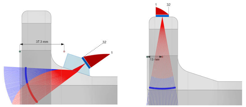
Figure 1: Inspection from taper surface (left), Inspection from hub (right)

Figure 2: Inspection from hub after reflection
The 2D CAD import is also compatible with the Total Focusing Method (TFM) technique allowing operators to inspect the sensitive areas of the flange in a multigroup configuration using Full Matrix Capture (FMC) or Plane Wave Imaging (PWI). In the following images, we used the same probes as the above previous example, positioning the region of interest (ROI) to focus acoustic energy along the flange bore, flange corner edge, and raised sealing face. We used a PWI acquisition to allow fast scanning speeds.
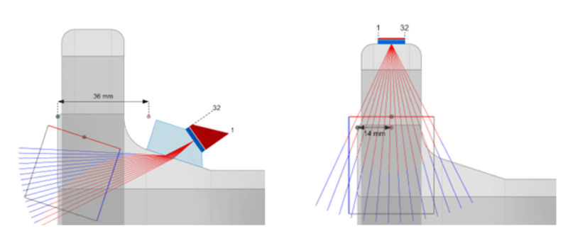
Figure 3: With the same probes, we position the region of interest to focus the acoustic energy along the flange bore, the flange corner edge, and the raised sealing face
The Complete NDT Solution for Detecting Flange Crevice Corrosion
The degree of test coverage achievable on each of these surfaces depends on the flange size and pressure rating. In other words, larger flanges with higher pressure ratings may require additional probes or equipment to ensure full test coverage. Flanges with higher pressure ratings often have more and larger diameter bolting holes, which can limit the inspection space between them, particularly on the bolt face. While the outer rim and bolt face are frequently used for inspection, it's worth noting that the taper neck provides 100% coverage of the sealing face. For these reasons, small footprint phased array probes are often used such as the 32L10-G1 with an SW55 wedge for the taper surface, and 32L5-G2 or 64L10-G2 for the inspection from the hub using a slider wedge to protect the front face of the probe.
One of the key benefits of Eddyfi Technologies’ advanced phased array systems is the ability to record data sets and analyze the data as complete scan files. This recorded data not only improves quality assurance and traceability, but also helps with pattern recognition when considering geometric responses from complex configuration. To perform an encoded scan, a suitable scanner is necessary. The versatile LYNCS™ scanner can be adjusted to scan from the tapered surface and the hub of a flange to provide full circumferential coverage of the sealing face. The LYNCS NDT scanner design is modular, and the magnetic tractors can be repositioned to help inspect with limited coverage. With a contactless encoder incorporated into the tractor, operators benefit from precise data acquisition and alignment. The following images show the LYNCS in a dual-sided configuration.
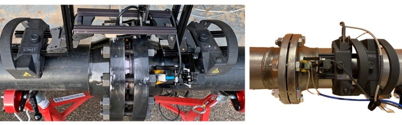
Figure 4: Dual-sided LYNCS configuration (left), and single-sided LYNCS configuration (right)
The ability to import 2D CAD files is a function of Capture software, and as such, is available for all three PAUT units: Mantis, Gekko and Panther. The Mantis is limited to 16-element apertures and is ideal for smaller flanges. The Gekko and Panther provide larger apertures and faster scanning speeds, especially when using the TFM technique. The following video shows the acquisition performed using the LYNCS in a single sided configuration performing a PAUT inspection from the taper surface with a 32L10-G1 probe and an SW55 wedge.
Flange Face Corrosion Detection Results
The sample is a RF 6-inch (152.4-millimeters) 150-B16 ISO-PN20-DN150 flange with machined corrosion. The drawings and an image of the front face are shown below.
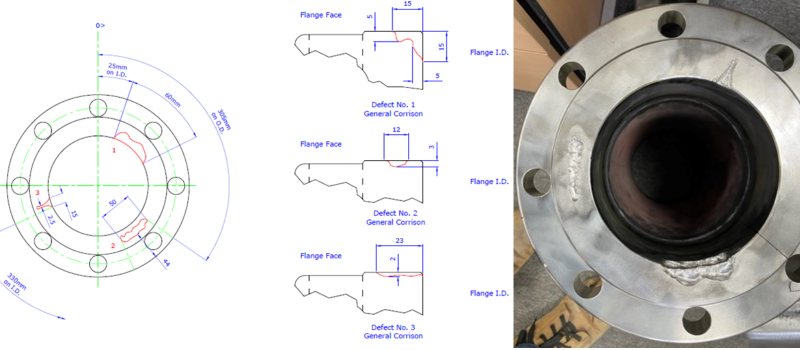
Figure 5: An RF 6 inch (152.4 millimetres) 150-B16 ISO-PN20-DN150 flange with machined corrosion
The following images show the NDT data results obtained with the single-sided inspection. The top image is the C-scan, the bottom images are S-scan with no corrosion (left), flange bore corrosion (middle), and flange face corrosion (right). The overlay of the sample can be seen in white.

Figure 6: Single-sided C-scan image
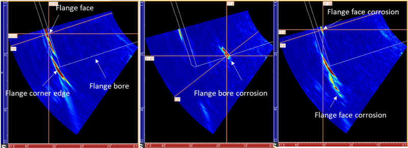
Figure 7: Single-sided S-scan inspection with no corrosion (left), flange bore corrosion (middle), and flange face corrosion (right)
When there is no corrosion present, the flange face produces a strong echo, while the corner edge produces a corner echo. However, if there is corrosion present in the flange bore, it will appear as an echo along the internal diameter (ID) surface of the bore. Flange face corrosion is detected by a shorter time-of-flight echo when first viewed at a very high angle and on the second leg. It is possible to export the data in the form of a 3D image of the flange.
As mentioned, it is possible to perform the inspection from several surfaces of the flange simultaneously. The following image shows a multigroup configuration with the 32L10-G1 positioned along the taper surface and a 32L5-G2 along the hub surface for the same circumferential position (Figure 8). Each S-scan brings different information about the flange bore corrosion that extends to the flange face; this is defect 1 in the drawings.
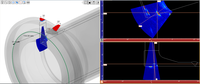
Figure 8: Multigroup configuration with the 32l10-g1 positioned along the taper surface and a 32l5-g2 along the hub surface for the same circumferential position
Talk about a game changer. Check out the complete evolution of Capture software here.
By importing 2D CAD files and defining scan plans directly on the equipment, the process of flanged joint inspections in the field becomes easier. This enables one to identify the best positions for probes along the various surfaces of the flange (including the bore, taper, or hub). By using the flange face echo as a reference, one can accurately position the probes along the flange. Moreover, the unique ability to map 3D data sets on predetermined CAD overlays enhances the visualization of information, thereby improving the probability of detection. Having a mechanical scanner that can encode phased array information and improve offline analysis is a significant advantage in terms of detectability and can provide asset owners with the assurance of inspection quality. In conclusion, the use of Eddyfi Technologies’ complete solution for flanged joint inspections can greatly enhance inspection efficiency and accuracy.
Contact our experts, or visit the Eddyfi Academy to learn more about how this technique can take your inspections to the next level!