
Phased array ultrasonic testing inspection of small-bore welds has been widely adopted over the past decade, replacing radiography primarily in carbon steel assemblies like power station boiler tubes with great success. When appropriate, the use of PAUT can bring several benefits to the inspection campaign.
Site safety and efficiency
Exchanging radiography for UT techniques removes the use of potentially harmful ionizing radiation from the local site, reducing the need for extensive safety protocols and associated costs. Where ‘hot’ work areas would previously be required to be closed for inspection to take place, PAUT can be carried out without exclusion zones, allowing regular work to be carried out alongside the inspection. With fully portable instrumentation, results can be analyzed directly at the point of inspection, or the data sent to a remote analyst for reporting. These give the site significant benefits in production efficiency and overall activity cost.
Inspection capability
While radiography can have its benefits, particularly for certain classifications of flaw, the use of PAUT can improve sensitivity to planar defects that may be difficult to detect with radiography due to mis-orientation. Additionally, PAUT techniques can give capability of depth and height sizing of indications, giving greater amount of flaw visibility for critical assessment and ability of rapid repair.
The challenge of small-bore stainless welds
First, what do we consider a small bore? This is typically circumferential butt welds in pipes having an outer diameter below 4-inch nominal pipe size (NPS). Typically, the welds have ‘thin wall’ cross section and weld caps in place, and due to the application, can have restricted access to allow for inspection scanners and non-destructive testing (NDT) equipment.
Of course, as with other techniques, stainless-steel introduces some additional challenges with regards to the conductance of sound waves, often being highly attenuative, distortive and scattering, reducing potential signal strength returned to the inspection probe and clouding inspection data with low level material grain noise. Additionally, should dissimilar metal welds or cladding be present, then inspection strategies and probe choice will need to be adjusted accordingly.
The small diameter of the pipes also creates a challenge, acting as lenses diverging reflected sound beams around a greater circumference, becoming more pronounced with the smaller the pipe diameter.
To inspect these components successfully the solution requires to take all these factors into account for a combined solution and it all starts with optimizing the ultrasonic probe design for the task.
Optimized probes
For austenitic stainless steels it is particularly imperative to ensure an optimal UT beam profile, concentrating the beam energy at the zone of interest and reducing loss due to divergence. With the use of 1D linear arrays there is no control of the beam in the secondary plane, i.e., along the length of the weld. This has been addressed for linear arrays by adding mechanical focusing of the elements in their width such as in the popular A15 probe for carbon steel boiler tube inspection. However, due to the need to keep the wedge low profile there is a relatively short sound path to the weld and a relatively wide beam profile in the secondary plane, particularly evident in thinner walled and smaller diameter specimens. Close to the wedge and early in the sound path, the beam profile may have a double maxima effect leading to oversizing and challenging characterization of indications in the extreme cases.
Dual linear array for small bore
One type of inspection probe approach to overcome some of the challenges of small-bore probes for austenitic material is the use of a pitch catch array probe which separates transmitter and receiver sound paths in the wedge with use of an acoustic barrier. The wedge is designed such that the interaction of the nominal beams in the material can occur at the area of inspection interest. Separating the transmit from the receive acoustically helps to reduce the background noise of the grain structure experienced with pulse echo probes by reducing the backscatter effect to the sensor which can be typical in these types of materials, particularly through long sound paths in thicker components. The dual linear array A25 probe and wedge can be useful in examining thicker austenitic pipes but may not be suitable for the very small piping.
.png?width=400&height=265&name=FIGURE%201%20-%20EDDYFI%20A25%20PROBE%20(WEDGE%20NOT%20SHOWN).png)
Figure 1: Eddyfi A25 probe (wedge not shown)
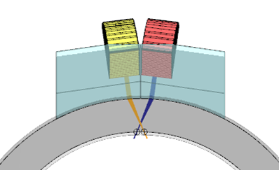
Figure 2: A25 pitch catch configuration for 60L wave in 2in NPS pipe with 5.5mm wall thickness
A 2D matrix probe approach
To overcome these challenges a low profile 2D matrix array probe has been developed which is compatible with existing small-bore scanners such as CIRC-IT scanners by Jireh and maintains a low-profile clearance to facilitate access restriction challenges. A 2D matrix array probe is diced in two dimensions so that elements can be fired independently and sequenced in focal laws to achieve focusing in both the primary and secondary planes.
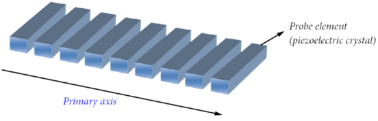
Figure 3: Dicing of 1D linear array
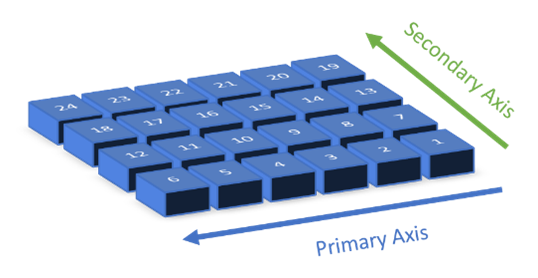
Figure 4: Example of a 2D matrix array
With the ability of the 2D matrix probe, it is possible to focus each beam both in the direction of the weld (primary axis) and in its circumference (secondary axis). This gives a much more uniform and tighter beam profile as seen in the comparison below example of a 3.5mm wall thickness 21.3mm OD stainless steel pipe.
A15 5MHz CCEV35 probe 16 elements with 60SW wedge – nominal 60SW beam shown.
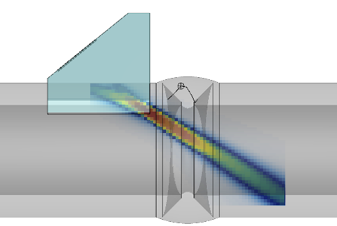
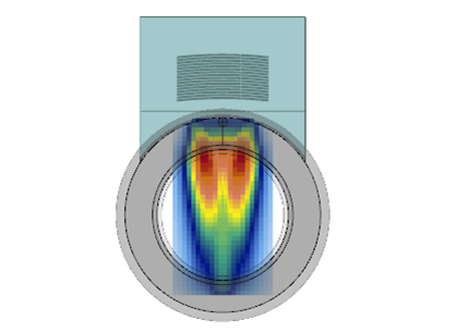
Figure 5: Beam profile primary and secondary axis
New M15 5MHz 63 elements 2D matrix probe with 60SW wedge – Nominal 60SW beam shown
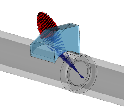
Figure 6: Contribution of 2D matrix elements for beam formation
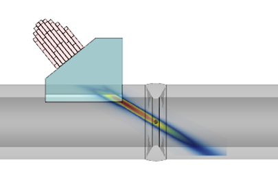
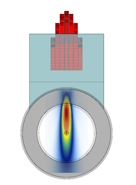
Figure 7: Beam profile primary and secondary axis

Scanner compatibility
Both the A25 and M15 probes can be coupled to the industry standard CIRC-IT scanner designed to cover circumferential welds from 21 to 114mm (0.84 to 4.5in) OD for rapid and precise encoded scanning. Both can be used either single- or double-sided with one of the Eddyfi PAUT platforms.
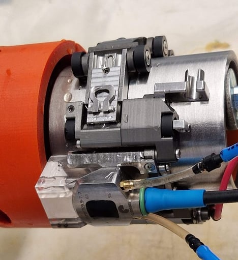
Figure 8: M15 matrix array probe with CIRC-IT scanner
CIRC-IT Features
- Accommodates standard pipes with diameters ranging from 21-114mm (0.84-4.5in)
- 11mm (0.4in) clearance, ideal for restricted access areas (< 12.7mm/0.5in)
- Enables one- or two-sided inspection in a single pass
- Easy setup and operation from a single side of a pipe row
- Ensures stable and consistent pressure throughout the scan
- Features smooth rolling movement with minimal axial drift
- Compact, lightweight, and portable design for enhanced maneuverability
- Facilitates quick and effortless wedge and probe changes
- Compatible with both ferromagnetic and nonferromagnetic pipes
- Boasts waterproof and rust-free construction
PAUT instrument platforms
Eddyfi Technologies provides several PAUT instruments ideal for this application. When operating the 2D matrix M15 probe, it is important to ensure that a 64 pulser instrument like the TOPAZ®64 or Gekko® is used as each focal law will comprise of all 63 elements of the probe firing. Thankfully the intuitive onboard software takes care of the 2D matrix array setup with ease without the need to create setups externally, and the probe can be calibrated and data collected with PAUT in the normal way. Onboard merged views, volumetric merge function, and advanced views greatly assist in the efficient analysis and reporting of data for operators with the flexibility to move to the powerful UltraVision® Classic for offline analysis if required.
As well as PAUT, both platforms offer live full matrix capture (FMC), total focusing method (TFM), phase coherence imaging (PCI), and plane wave imaging (PWI) acquisition modes which can be fully utilized with the 2D matrix array technology where it brings benefit to the inspection.
Results
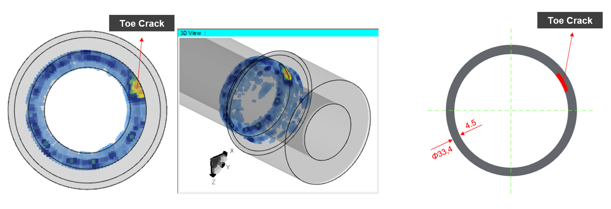
An example of the results on stainless steel thin wall material can be found in this interesting application for inspection of stainless-steel small-bore socket welds. The sample here, provided by HOIS, is a socket weld of 1in NPS, having an outside diameter of 33.4mm in the fitting. The wall thickness is 4.5mm.
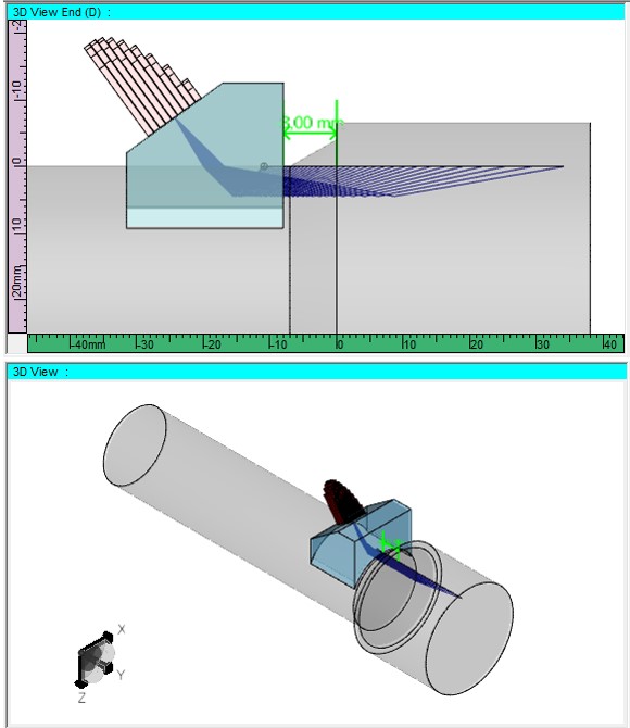
Figure 9: Scan plan - M15 2D matrix on socket weld
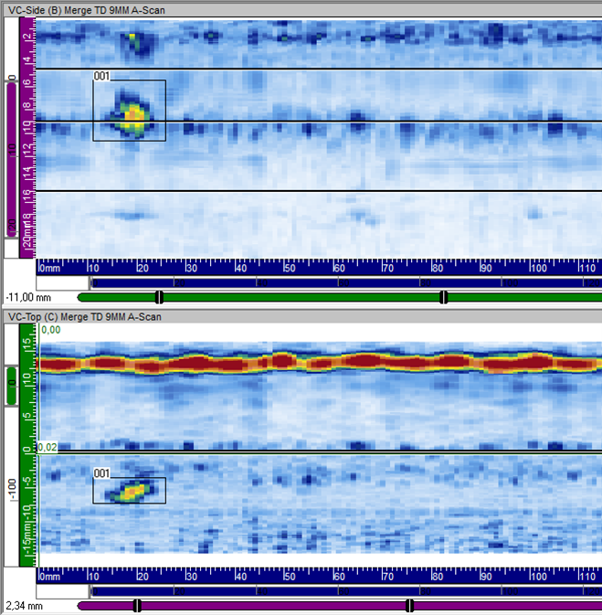
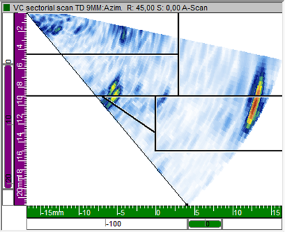
Figure 10: Data of stainless-steel socket weld showing toe crack
Advanced focusing methods
It is also possible to utilize advanced focusing methods, such as TFM from FMC or PWI live, or through post-processing when raw FMC or PWI data is acquired. UltraVision analysis allows the post-processing of this data in a number of different algorithms which can drastically improve signal-to-noise ratio (SNR) for indications in challenging materials.
For example, during inspection of a stainless-steel small-bore weld sample, it was found that through post-processing of acquired PWI data using the phase coherence factor (PCF) algorithm, the response from a single isolated pore embedded within the weld was greatly enhanced.
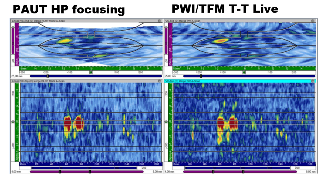
Figure 11: Data from 4mm wall thickness stainless-steel weld
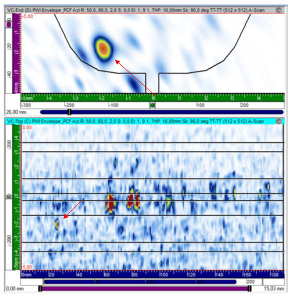
Figure 12: PWI data reconstructed using PCF TT-TT path, showing isolated pore in weld
Summary
Eddyfi Technologies’ leading instrumentation and software coupled with an optimized probe approach brings small-bore stainless-steel weld inspection to the next level.
Probe selection and UT approach is the foundation of a successful inspection. The new M15 2D matrix array probe for small bore inspection, greatly improves the beam profile to improve characterization, detection and SNR when it matters most.
Eddyfi Technologies’ fleet of instruments including the TOPAZ64 and Gekko are ideal for taking advantage of this advanced probe technology and support setup of 2D matrix arrays onboard.
For a more technical review, check out this blog.
For more information, check out this webinar on the topic, and contact our team of experts ready to offer a Beyond Current solution to your inspection challenge.